Hi,
Then consider buffering the inputs.
I would probably suggest to instead keep simple ones and bootstrap the CCS AND the cascodes to the common mode signal. It can be done using a minimal number of extra parts and they are all resistors.
The CCS's should do much better (as you effectively keep the voltage conditions under which they work constant) and the cascodes now rigidly lock the voltages across the amplification transistors without common mode related swings.
Ciao T
Thorsten, I do have an active, fully complementary buffer for it. It should be on the "Input board", which is also to contain XLR sockets and associated electronics (optional, i.e. in two versions, just an RCA Cinch buffer, or the same plus XLR).
It's as vanilla as they come, so I didn't bother posting it. I can if there's an interest for it.
As for the CCSs, as you say, since any I use is fed off regulated voltages in all cases, I am probably not likely to not encounter quite a bit of the usual problems with them. Those shown I picked from a Siemens engineer's project from somewhere, I think (but am not sure) it was from an Elektor MOSFET amp article many years ago. I've since used it and it seems very good to me, but I could be wrong.
Regarding your suggestion, I would once again beg for a schematic (hand jotted is just fine), as I am not sure what exactly do you have in mind.
Well, re-ran all the various IPS and VAS bias and current source options. My conclusion is that the distortion is dominated by the output so not much of anything I do has more effect than trading half a dB between even and odd harmonics. The sim puts things at about .003% second and .001% third. Quite a bit better than the original on odd. Need to order a few resistors and NPO caps. This has been a lot of fun, but I still don't know what makes the Rotel sound better to my wife!
I am going to play with all the other ideas on the MX-50 boards as they are a lot easier to work on and don't have expensive outputs.
I am going to play with all the other ideas on the MX-50 boards as they are a lot easier to work on and don't have expensive outputs.
Attachments
Well, re-ran all the various IPS and VAS bias and current source options. My conclusion is that the distortion is dominated by the output so not much of anything I do has more effect than trading half a dB between even and odd harmonics. The sim puts things at about .003% second and .001% third. Quite a bit better than the original on odd. Need to order a few resistors and NPO caps. This has been a lot of fun, but I still don't know what makes the Rotel sound better to my wife!
I am going to play with all the other ideas on the MX-50 boards as they are a lot easier to work on and don't have expensive outputs.
Try the split compensation as described by Self in LA Vol. 0. One more cap, one more resistor, and the output stage distortion is reduced by being partially inside the integrator loop. I see lots of benefits and so far no drawbacks.
are you referring to "Transitional Miller Compensation" Edmond Stuart re-invented, promoted here? – the R leg of “2-Pole” “T” connected to the output instead of AC gnd as in “2-pole” compensation?
both “TMC” and “2-pole” compensation really require the added gain of the “Beta enhanced”, input buffered VAS to show large benefits
It took several of us lots of posts to get across the fact that "Two Pole" compensation can give near identical results to "TMC" in the Cordell Book thread
which seems at 1st glance to leave little reason to choose between them - Except for the misinterpretation that "TMC" loop gain as naively measured makes it look like you still have "single pole" global loop gain roll off - giving the False impression of greater loop stability than 2-pole comp
my post: http://www.diyaudio.com/forums/soli...lls-power-amplifier-book-134.html#post2420438 shows “TMC” apparent gain/phase margin in global loop measurement falls apart with the added delay sim ( “CMC” = conventional Miller comp )
to properly measure, compare "TMC" and "2-pole" compensation you have to measure total feedback loop gain around the output devices: "inside" the TMC inner loop - both compensation techniques can be adjusted to give very similar loop gain curves, gain, phase margins
when trimmed to "the same" equivalent loop stability margins, loop unity gain intercept frequency they are seen to be nearly equivalent
I prefer 2-pole on the grounds that the added gain is visible in the global loop and therefore additionally linearizes the input diff pair vs TMC
Last edited:
are you referring to "Transitional Miller Compensation" Edmond Stuart re-invented, promoted here? – the R leg of “2-Pole” “T” connected to the output instead of AC gnd as in “2-pole” compensation?
both “TMC” and “2-pole” compensation really require the added gain of the “Beta enhanced”, input buffered VAS to show large benefits
It took several of us lots of posts to get across the fact that "Two Pole" compensation can give near identical results to "TMC" in the Cordell Book thread
which seems at 1st glance to leave little reason to choose between them - Except for the misinterpretation that "TMC" loop gain as naively measured makes it look like you still have "single pole" global loop gain roll off - giving the False impression of greater loop stability than 2-pole comp
http://www.diyaudio.com/forums/soli...lls-power-amplifier-book-134.html#post2420438 shows “TMC” apparent gain/phase margin in global loop measurement falls apart with the added dalay sim ( “CMC” = conventional Miller copm )
to properly measure, compare "TMC" and "2-pole" compensation you have to measure total feedback loop gain around the output devices: "inside" the TMC inner loop - both compensation techniques can be adjusted to give very similar loop gain curves, gain, phase margins
when trimmed to "the same" equivalent loop stability margins, loop unity gain intercept frequency they are seen to be nearly equivalent
I prefer 2-pole on the grounds that the added gain is visible in the global loop and therefore additionally linearizes the input diff pair vs TMC
Yes, as you describe, transitional Miller (I'd first seen it in the Self reference, probably breezed past it in Cordell...). Haven't followed the thread in here.
I was skeptical that it would help here as much as it does, but I see a ~25dB improvement (!) in sims. I do not have precise models of the output devices tvrgeek is using, but the improvement effect should be more-or-less independent of those.
With a more elaborate design, JFET cascoded input devices*, better transistors all around, beta enhancement stage inserted in second stage, much better current mirror of the "e-follower" type for balancing load currents, bootstrapped cascode for second stage .... I see ridiculous performance from a meter-reader perspective, clearly unbelievable but intriguing nonetheless as it doesn't entail a lot of effort or expense. Of course the input stage and its cascode parts are assumed perfectly matched. I also beefed up the second stage current and as well raised the emitter resistor value so that the bootstrapping would be more effective (to ~55 ohms, 10mA stage current, output CB stage an MPSW92 for better dissipation capability).
Oh, and transient response looks very clean indeed. Frequency response is about -3dBr at 550 kHz at the output (not looking after the L-R decoupling).
*that is, bipolars with the 47 ohm degen Rs and JFETs on top, with the gates tied to the bipolar emitters. Some voltage drop is needed in the JFET drains to avoid exceeding breakdown voltages.
Last edited:
Try the split compensation as described by Self in LA Vol. 0. One more cap, one more resistor, and the output stage distortion is reduced by being partially inside the integrator loop. I see lots of benefits and so far no drawbacks.
Waiting for payday to send a pile of my money to Jan for his mini-books. I have always found him worth reading. This was car insurance month.

In the mean time, there are about the next 200 pages of the Spice manual to digest.
Gasp, has the price of copper gone up. $200 for the coils for a speaker prototype I am working on. It is almost cheaper to go electronic.
I will probably go ahead and order a handful of 2SA970 and 2SC1085's for the half or so positions that are within their limits. (input and top of cascode) I have not found anything still in production that would seem to better the existing for the rest.
Exicon models attached. I found them on one of these threads. The models ending in "c" thanks to Mr. Cordell.
Attachments
I have the diagram of the two pole. I have been a little timid as it was not easy getting the real amp to be stable on the bench. 33p CMC with the 3.3p in the feedback did the trick.
I see models of 2SC1775 and 2SC992. I would love to have them.
I did try extending the CMC cap to the driver stage. Sang like a bird. So there is clearly something I don't understand about that. The above link I am going to have to print to study.
That I did not notice much difference adding degeneration on the IPS CM I am assuming is that with perfect parts, they have little effect. The benefit is with real parts? Same with adding a cap across the bias spreader.
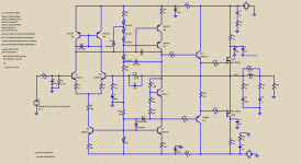
The thing I could not improve on in balancing the idle current between the P and N outputs. Once I got the sim to behave, I found whatever I did did not cause much difference, so is 10% "close enough"? , 110mA and 121 mA. Upping to 125 or so in the sim did not do well, but I sure plan on doing it for ear.
the .01 resistors on my drawing are there just so I have a quick place to measure idle current. They are not real.
I see models of 2SC1775 and 2SC992. I would love to have them.
I did try extending the CMC cap to the driver stage. Sang like a bird. So there is clearly something I don't understand about that. The above link I am going to have to print to study.
That I did not notice much difference adding degeneration on the IPS CM I am assuming is that with perfect parts, they have little effect. The benefit is with real parts? Same with adding a cap across the bias spreader.
The thing I could not improve on in balancing the idle current between the P and N outputs. Once I got the sim to behave, I found whatever I did did not cause much difference, so is 10% "close enough"? , 110mA and 121 mA. Upping to 125 or so in the sim did not do well, but I sure plan on doing it for ear.
the .01 resistors on my drawing are there just so I have a quick place to measure idle current. They are not real.
My original point was that THD, (T)IMD, DF and co are advertising numbers, not technical engineering specifications.
THD and IMD as emotionally loaded advertising spec (who would want greater total distortion) would relate to a single and two tone FFT with the individual harmonics extracted and weighted to give us an indication of audibility as emotionally neutral engineering specification.
So, if we had an amplifier whose THD exceeded the threshold of audibility for any individual harmonic, then harmonic distortion would be inaudible.
Instead THD and IMD suggest a relation to audibility that does not exist.
You seem a bit confused here Thorsten. Perhaps you'd like to go away and think about this one again?
So, if we had an amplifier whose THD exceeded the threshold of audibility for any individual harmonic, then harmonic distortion would be inaudible.
Learning something from natural sciences, we always try to create models, that reflects major properties of definite natural phenomena. In many cases these models help us to explain and to predict, but sometimes they do not reflect certain second-order properties of the phenomena considered.
I would try to distinguish between amp's models and measurements, based on the models, and real properties of amps revealed at listening sessions.
One should not believe that audio reproduction is completely correlated with simple model based tests. This fact is obvious to everybody who paid definite attention to building of his audio system.
On the contrary, there is a multitude of persons in audio industry, who are INTERESTED to simlify the situation and to make the market game more simple. Some academicians are interested to produce an opinion, that they really have everything under understanding and control in the field of audio, otherwise their status will be under doubts.
Last edited:
Vlad, yes.
This is all about what I can change to see if it has an effect on the elusive unknown distortion that makes trumpets bother my wife. I am not a numbers guy per say, they are informative and most important when repeatable and relative to each other. We established a long time ago there is no all encompassing number to advertise that tells you how it sounds. It is exciting to model something that drastically changes the result of the same basic amp, as that has a reasonable probability of changing the sound. The rest of the changes did not change the model enough to suggest they may change the sound. The members of this forum have been most helpful in getting me on that first step to understand how amps work so I can actually make changes. The only thing discouraging is that I am on the first step looking at a 10 story building.
My original working hypothesis is high order distortion causing the tweeter to be unhappy. I put a 2 pole, 18K passive LP filter on the tweeter. No change. Now what?
So:
Is a reduction of an order of magnitude going to make an audible difference?
What is the RB-951 doing or not doing that either masks or does not cause this problem?
If I apply a similar technique to it, will it make it audibly better or worse?
What does this say about the simple is better camp vs the correct it camp?
If it is a total failure sound wise, but measures at lab grade spec, then I still win as I have a bench amp that is better for measurements!
Transient response looks better than original too. Spice-wise at least. In THEORY, as humans have about 130 dB dynamic range between inaudible and pain, including permanent damage to our hearing, the above configuration would be perfect. Too bad we don't live in perfect.
Now,
Is there a plus or minus to adding a trimmer, 500 Ohms or so, in parallel with the 100u cab that sets LF roll-off to trim the DC offset? What is acceptable on the output? 100mV? 200? Or is it far more susceptible to thermal drift and best to leave alone? (yea, I know, servo but I am trying to keep this simple)
What about current feedback vs voltage ......?
Please explain.
I am going to put this on.
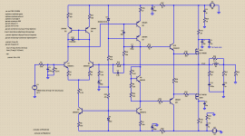
A resistor of 1K or so should be added in serial with Q9 base
to prevent any device saturation to suck up the whole
bias current and disable the differential s current source.
A better path is to add simply a second 47K resistor and diode
to have separate voltage references for the two current sources.
...
A better path is to add simply a second 47K resistor and diode
to have separate voltage references for the two current sources.
That's what I'd do. Sharing of resources somehow always brings its own baggage, better not play with it, especially since the added complication and cost is truly negligible.
My original working hypothesis is high order distortion causing the tweeter to be unhappy. I put a 2 pole, 18K passive LP filter on the tweeter. No change. Now what?
So:
Is a reduction of an order of magnitude going to make an audible difference?
What is the RB-951 doing or not doing that either masks or does not cause this problem?
Now,
Is there a plus or minus to adding a trimmer, 500 Ohms or so, in parallel with the 100u cab that sets LF roll-off to trim the DC offset? What is acceptable on the output? 100mV? 200? Or is it far more susceptible to thermal drift and best to leave alone? (yea, I know, servo but I am trying to keep this simple)
One thing you might find amusing is to do a differential comparison of the Rotel and your refurbished Hafler. Tweak the levels for the best null, initially just with flat gain adjustment, possibly some phase adjustments thereafter if you have the patience. Listen to the signal across a speaker (or headphones, but be careful not to blow them out with overvoltage) between the outputs. It's not the whole story, but you may find some prominent differences, like frequency response differences.
As far as trimmers, I'd avoid them, particularly in the feedback network. They are notorious for being flaky, and you are trying to use bias/offset current to set the d.c. offset overall, and I suspect the drift in this is going to be fairly large. This input configuration, unballasted simple current mirror, and unbuffered second stage together are prone to mismatch errors and drift. But the a.c. coupled feedback should prevent things from being too far out of line.
Please explain.
Some amplifiers use current feedback network instead of voltage, maybe T, or Brad could explain why and if applicable for you ..
- Status
- Not open for further replies.
- Home
- Member Areas
- The Lounge
- Sound Quality Vs. Measurements