mc - direct to digital with superconducting ADC?
Digital-RF Receiver | Hypres Inc.
if this follows the plots in their 2009 paper it should do over 20 bits @ 96k - with few 10,000x oversampling ratio may not blink at mistracking either
Digital-RF Receiver | Hypres Inc.
if this follows the plots in their 2009 paper it should do over 20 bits @ 96k - with few 10,000x oversampling ratio may not blink at mistracking either
Last edited:
Time for a response,With all the brainpower collected here, we still don't have the answer it seems.
I do know that the answer is not 42.
Dan.
And just about no engineers, or anyone with technical competence worry about getting that right ...
Frank
Last edited:
Settling time and slew rate are two ways to look at the speed of an OPA. One for little signals, one for large onesMy question concerns "settling time".
If you could read the plots you might see the difference in sensitivity to interference. It clearly shows that JFETs are superior to BJTs in this.
I did read the plots, and yes opas with jfet input are superior.
I would have asked to show further harmonics with the 1k signal but your test equipment does not reach 100khz. I don't think any sound card AD is adequate even to measure thd20.
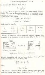
Affect of skin-proxy effects -
This is also shown in text books, Like this one from my library - Elements of Engineering Electromagnetics by N.N. Rao. Though the effect isnt as straight line as in this theory.
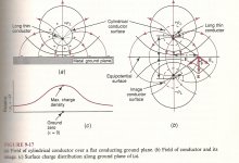
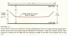
I was thinking of B fields but if its clear that high frequencies must be where the L is lowest... skin effect. Charge density is another view.
What is the effect's relevence to audio?
Skin affect and proximity affect at real world wire size, parts and all adds about 10-20% increase in R. Or about 15 to 1 increase over dc R (Rdc to Rac). Attachment #5 shows it gets complex fast when you get away from simple wires. The job we have is to reduce that ratio. Thx-RNMarsh


 View attachment 325772
http://www.phys.uri.edu/~gerhard/PHY204/tsl243.pdf
jn
ps..Becker had the same text, I was actually looking for a drawing online which shows it. For now, the calculations from some code I wrote. Top is the wire, bottom is B. Note it rises linearly from wire center to wire surface, then as 1/R out of the conductor.
pps. Found some with supporting pictures, all ya hafta do is google "magnetic field inside wire", the nj ppt link is an AP physics course for high school. Page 8 has the equations, 9 has the drawing. I won't copy the drawing and paste it here, but it basically duplicates the drawing I posted.
This is also shown in text books, Like this one from my library - Elements of Engineering Electromagnetics by N.N. Rao. Though the effect isnt as straight line as in this theory.
I was thinking of B fields but if its clear that high frequencies must be where the L is lowest... skin effect. Charge density is another view.
What is the effect's relevence to audio?
Skin affect and proximity affect at real world wire size, parts and all adds about 10-20% increase in R. Or about 15 to 1 increase over dc R (Rdc to Rac). Attachment #5 shows it gets complex fast when you get away from simple wires. The job we have is to reduce that ratio. Thx-RNMarsh


 View attachment 325772
Last edited:
What is the level where it is no more important ?
IMO under the DUT noisefloor, same applies for 8th and above. HD spectra should be checked at 50, 1k and 20khz. THD should be checked at 20k with a multitone signal.
It would be nice if we could rely on simpler measurements, but they led astray many audio designers in the 70s and still do today.
I do not have OPA211, sorry.
PMA, if you want you can pm me your address and I will send you one Reason is that the OPA211 really looks interesting on paper and from what I can measure is quite excellent and also sounds right. But I can't see as deep with my measurement setup as you can.
Nice to see they are still in business. I remember the earliest product and wondered if they could survive.Digital-RF Receiver | Hypres Inc.
if this follows the plots in their 2009 paper it should do over 20 bits @ 96k - with few 10,000x oversampling ratio may not blink at mistracking either
Chris, I think I have the Boyk-Sussman paper, I'll check tomorrow from PC and attach if I do. I have read something from Sussman and he definitely was on the right track.
Here's a link: http://www.its.caltech.edu/~musiclab/feedback-paper-acrobat.pdf
I always thought that measurements, and specially THD were proposed to help designers to improve their designs, and optimize values, not more. It is the marketing guys witch had used-it for commercial argues. Look, Telstar, even here, nobody can agree their valueIt would be nice if we could rely on simpler measurements, but they led astray many audio designers in the 70s and still do today.
If I may add my $0.02 of experience. Some OPA characteristics are only poorly understood and receive little attention among the Golden Pinnae. Here are 3None of the good opamps (OPA627, AD797, OPA134 ...) has any residual 7th above -120dB. They do not sound same, but the 7th is not the reason.
Hello again Pavel, I respect your measurements data, that said it reads that you are making subjective comment here. Could you please elaborate on your subjective findings of these opamps, or at least your subjective findings of differences between this collection of opamps.
- RFI immunity. Pavel has said a lot about this. It is particularly important with the unbalanced leads used by the Golden Pinnae. IMHO, in microphones, it is one factor that distinguishes the Great Mikes from the toys.
- Requirement for good decoupling & layout. Naive decoupling as in JC2 Mk1 is practically guaranteed to ensure OPA627 AD797 & the new uber OPAs will not meet their low distortion potential and exhibit insidious stability even if they do not burst into oscillation.
- Many of the new uber OPAs exhibit the 'latching and phase reversal on overload' you get with TL07x family.
I'll pontificate on why OPA134 family seems to come recommended even though, these days, its spec is quite mediocre as measured in simple circuits, ie test rig. It does VERY well on the above 3 points compared to practically all other supa OPAs and the new uber OPAs.
There was a long thread (can't find it so must be on another forum) where someone was trying to 'improve' an old mixer by swapping OPAs.
Lengthy advice by many gurus and some pseudo gurus (ie yours truly) led him to revamp the earthing and decoupling system. (It's really quite difficult to do earthing & decoupling properly on a large & complex system like a broadcast mixer. Which is why an old Calrec will have a MUCH better spec than cheaper stuff though they appear to use the same ingredients) This improved THD by 20dB overall and even more in specific circuits.
Now it was much easier to see the difference between OPAs, including THD and little bursts of oscillation which he laboriously dealt with. OPA134 gave the best overall THD c/f with several supa stuff that have been mentioned on this thread.
IMHO, this is cos, even with much improved decoupling & earthing, the other supa & uber OPAs needed still better attention to approach their potential performance. The less fussy OPA134 was closer to its potential performance.
Looking at the datasheet spec and making 'calculations' doesn't absolve you from measuring the complete device to see if your 'calculations' are correct.
One of the new uber OPAs tried was LM4562 which I believe is LME49710 family with a different cheaper process. This has latching and phase reversal issues. It is inappropriate for simple single supply circuits and also certain filter & EQ circuits.
While the above is obviously slanted towards pro-mixer design, it will have audible consequences in simpler Golden Pinnae design too ... eg where using 'stuff hand carved by virgins from solid Unobtainium' takes priority over basic layout & decoupling considerations. The AD797 datasheet covers important points on decoupling which EVERY user should follow.
Layout is a more 'black art' issue where, from the circuits presented on this thread, even (pseudo?) gurus may need further study.
BTW, humble 5532/4 benefits from the recommendations in the AD797 datasheet. When properly implemented in real applications, it often rivals the new uber OPAs. It's evil unique Class B output stage is particularly clever with vanishingly small 7th harmonic.
Last edited:
Richard, this seems a point overlooked again and again in the audio world, to its continuing detriment. The better the part or component the better it has be designed in, or integrated. Sloppiness will always be penalised by injecting higher levels of objectionable, audible artifacts.IMHO, this is cos, even with much improved decoupling & earthing, the other supa & uber OPAs needed still better attention to approach their potential performance. The less fussy OPA134 was closer to its potential performance.
The only measurements that count, are those of a complete system, under stress - meaning amplifiers working hard into nasty loads, lots of mains and RF interference in the mix. Ivory tower spec'ng and verifying doesn't cut it as far as the ear/brain is concerned ...
Frank
Pavel
Congratulations on your payment of tuition at the John Curl school of audio design. Your work and measurements that John likes will be used in his designs
So now it is your opamps and my resistors.
Brad
You previously asked how some of the issues relate to the BT thread.
The stuff I have been trying to show are almost all incorporated in the BT. However JC has noted a few new twists.
One of the new uber OPAs tried was LM4562 which I believe is LME49710 family with a different cheaper process. This has latching and phase reversal issues. It is inappropriate for simple single supply circuits and also certain filter & EQ circuits.
The LM4562 and LME49720 are the exact same die. The part numbers were rolled to add the part to the rest of the new audio focused NS lineup. Nothing more or less. You can get them in metal cans, which are reputed to sound better. Improved EMI resistance?
Swapping opamps casually is like swapping dual triodes with no effort to adjust the circuit. Its frustrating but necessary to look at the details of the circuit before swapping or anything may happen. Most non-audiophile products are built to minimum specifications for performance and when the specs are met development stop and they are tested for emi compliance, safety etc.which will catch many of the problems that audiophile products are often susceptible to. Casually swapping parts can upset a very carefully balanced applecart.
I always thought that measurements, and specially THD were proposed to help designers to improve their designs, and optimize values, not more. It is the marketing guys witch had used-it for commercial argues. Look, Telstar, even here, nobody can agree their value
Of course. Measure it. If the distortion is too low, it must have too much feedback, so tell the engineers to make it higher and then claim no feedback or low feedback.
Its what the people want. So give to them.
My interpretation. Not necessarily my view . . .
"Improved EMI resistance?""
Nothing to improve that will add real value if your system design and layout are well done. They are using these things in soundcards sitting on MTBDs with wideband hash
(digital and PSU) in a metal box and still deliver better than -120dB - with some even 10 dB better than this.
Nothing to improve that will add real value if your system design and layout are well done. They are using these things in soundcards sitting on MTBDs with wideband hash
(digital and PSU) in a metal box and still deliver better than -120dB - with some even 10 dB better than this.
The LM4562 and LME49720 are the exact same die. The part numbers were rolled to add the part to the rest of the new audio focused NS lineup. Nothing more or less.
Bob Pease told me the number was changed because in another language LM4562 sounded like a word you would not use in polite company.
Bob Pease told me the number was changed because in another language LM4562 sounded like a word you would not use in polite company.
That reminds me of at least a few stories along similar lines. One was that Enco (anyone remember that gasoline brand?) meant "stalled car" in Japanese.
- Status
- Not open for further replies.
- Home
- Member Areas
- The Lounge
- John Curl's Blowtorch preamplifier part II