That would show up in my (broad) 'performance' catagory.Richard, it is more than that. It is using the RIGHT part for the job.
Last edited:
Then, Richard, you are not explicit enough.
For me, having the RIGHT switch, designed to do that SPECIFIC job meaning current-voltage as good and clean as possible. This usually means gold-on-gold switches, but silver on silver switches can be even better in some circumstances.
Another alternative is some 'typical' switch controlling a set or many sets of relay contacts. There, gold-on-gold is usually best.
This also means to avoid 10A switches to control .001A. This is because gold usually blows off with 2A or more, and you get a more base material that can be easily tarnished, and therefore compromised.
Many here have no knowledge of this. Others just ignore it. Yet it can make a serious difference in listening quality. You cannot necessarily look at a switch from the outside and know its internal characteristics. That takes further investigation and study. Study up everybody! '-)
John did define quality in the post you were answering to. Do you read
your own posts only ? Is your only goal to make comments like the one
you just did ? Probably quality means nothing to you, but for others it does.
Good accuracy .......

Scott,
I don't think you got my reference to the parable of the blind men and the elephant. Each looked at parts and thought they had the whole.
Making standard measurements of the AP is mostly autopilot. If you don't pay attention to the details you get very pretty graphs of nonsense.
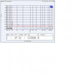
Attached is a THD curve that shows the noise limit and the maximum voltage out of the unit. (It gave me an error message when I tried higher source voltages.)
The second attachment is the best curve of the LM4562 as there is a gain of about 100 be sure to reduce the label values.
I showed you the current source version of the test circuit as shown in the data sheet. Now from prior questions it seems almost no one here can even write the loop equations, which I thought were obvious from inspection.
Trying to get the same view of the Elephant how do you read the limit of the AP trying to display what is shown?
ES
PS I see I forgot to do log on the voltage so the graphs don't look the same!
Ed I'm not here to teach EE101 end of this chapter. If the equations are obvious why can't you write them?
About the setup to increase distortion a good basic explanation is given in the opa134 specsheet http://www.ti.com/lit/ds/symlink/opa134.pdf

This is the relevant part and I hope it reads well. It is easy to see that the input impedance is defined by the input impedance of the opamp. If R1 is included. It is a voltage divider consisting of R1 and R2, which keep the voltage at the inverting input at the voltage at the non-inverting input, which is Vo of the generator. No current flows through R3, except most part of the error voltage. In case R1 is omitted, so for G=1, the situation is identical, since Vo of the op amp is now identical to the Vo of the generator, bar again most of the error voltage.
I think Scotts explanation using the concept of bootstrapping is a bit misleading. Nothing is really bootstrapped as I see it, except for the error part, it is like reverse degeneration. The input impedance seen by the generator is exactly the input impedance of the opamp, plus whatever error voltage has to be sunk. But that is minute.
Nice little experiment for a Sunday afternoon: by replacing R3 with a small pot, one can have a continuously variable distortion component at an opamp output. I did this when I started working with OPA134, just to hear when stuff becomes audible and because I like the smell of rosin core in the morning.
Last edited:
About the setup to increase distortion a good basic explanation is given in the opa134 specsheet http://www.ti.com/lit/ds/symlink/opa134.pdf
View attachment 323428
I think Scotts explanation using the concept of bootstrapping is a bit misleading. Nothing is really bootstrapped as I see it, except for the error part, it is like reverse degeneration. The input impedance seen by the generator is exactly the input impedance of the opamp, plus whatever error voltage has to be sunk. But that is minute.
If you have an input resitor and drive the other end with a replica of the input voltage so the resistance appears much larger to the driving signal I call it bootstrapping as it is in general use.
Avgolemono ! For some fat, tasty soup, a pie or for roast dressing ? Try a bit of oregano or thymus in it.
George
Yesterday just the soup, I wasn't kidding around 1969 while I was at MIT there was a nice Greek community here in Central Square and I miss the comfort food I even made a batch of lamb shanks last month.
For me, a crucial attribute of quality is that the characteristics are maintained with time, or improve. If a supposed high quality item starts well but then degrades while in its normal operating environment for no other reason than it's just doing its job, then for me the "quality" is not there. Pots fall into this category, as do standard methods of connection.About pots, my question was not so insane: what can-we measure to ensure a pot is a "quality" parts. Of course, i got no answer.
No, or we don't have the same definition of "define". It is like "Right part".
I would be far happier using a lower grade item which stabilised in its characteristics with time, than a "gold plated" unit which I could be aware was losing its "polish". The tension of hearing, and waiting for the qualities to "go off" is not worth it ...
Frank
What , I thought all IC guys were Vegan ......
You mean sheep are not vegetables?
If you have an input resitor and drive the other end with a replica of the input voltage so the resistance appears much larger to the driving signal I call it bootstrapping as it is in general use.
Well, my point is that you don't see a replica of the input voltage to lower the resistance to the driver signal, so there is no bootstrapping there.
Let me refer back to you post #32541
The signal gain is one and since the 10 Ohm resistor is bootstrapped by the Aol of the op-amp (divided by the feedback factor), the input resistance is very large, any bench generator has no trouble driving this +-10V. ALL errors refered to the op-amp input noise, CMRR, distortion, etc. have a gain of 101 to the output. Do you really not see that? Simply consider a nearly ideal op-amp put 10V on the + input the op-amp forces the - input and the output to 10V by feedback i.e. there is no current in either resistor, the circuit acts like a gain of 1 follower, and the input resistance is very large. If need be say the op-amp has an Aol of 10^6 so 10uV appears across the 10 Ohm this is all the generator needs to supply i.e. the input looks like 1Meg Ohm.
Since I am following the threat on a discrete opamp with interest, and have learned a lot of your insights there, it is with great trepidation that I go against your statement here.
1. Both + and - inputs of the opamp will be at the same potential, regardless of the Aol of the opamp.
2. Therefore, the 10 Ohm resistance will carry no current, this with a perfect opamp.
3. With an imperfect opamp, only the error signal will develop over the 10 Ohm resistor.
4. This error signal is all the signal generator will see, this plus the input impedance of the opamp.
JN
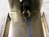
You are a grrfter nerzzog frakidle! Attached is a picture of the test setup and the FFT with the wires close a shown and then pulled back. The third harmonic is identical and extremely low. That would be from resistor distortion not quite being the same. There is a clear spike on the second harmonic with the wires close. It is greater than the thermal distortion.
As this took me 4 hours I am not inclined to do much more.
But the peanut gallery as usual is arrogant and wrong.
ES
Attachments
About pots, what did-you think about PGA23XX ? With no contact noise, no wear, and a HD+n of ~0.0002%, i think we can consider those as "quality" parts despite the low price ?
It would be great, if you have some more time, to compare various film resistances brands, to figure out if any measured real difference ?
Thanks a lot for your effort, Ed. It was very interesting.As this took me 4 hours I am not inclined to do much more.
It would be great, if you have some more time, to compare various film resistances brands, to figure out if any measured real difference ?
Last edited:
JN
You are a grrfter nerzzog frakidle! Attached is a picture of the test setup and the FFT with the wires close a shown and then pulled back. The third harmonic is identical and extremely low. That would be from resistor distortion not quite being the same. There is a clear spike on the second harmonic with the wires close. It is greater than the thermal distortion.
As this took me 4 hours I am not inclined to do much more.
But the peanut gallery as usual is arrogant and wrong.
ES
No you are wrong and don't even know it.
Ed I'm not here to teach EE101 end of this chapter. If the equations are obvious why can't you write them?
A few reasons, it is a pain to type equations, when I present EE100 level questions almost no one gets them, those folks who do try are ridiculed by the peanut gallery.
To recap for the peanut gallery, this exchange started out by George and I discussing resistor distortion, when I mentioned that opamps today can be limited by the passive parts and cited the LM4562. I then mentioned I thought that it was mismeasured it went off on a tangent.
My feel is that they got an AP and used it to produce lots of wonderful pictures but did not quite have a grip on it's limits. It seems that when you measure THD it looks at the frequencies above the fundamental. As a result for the same level of distortion as the frequency rises the displayed result drops. The second issue is the base noise level of the AP when in the THD mode. When a human looks at THD today they should be using an FFT with adequate resolution and often averaging to reduce noise. They can then pick out distortion from noise. Using autopilot may not do that and be misleading. The final issue exactly which circuit did they use at first to make measurements. Scott points out that AD does it correctly and presumes other do also. (Which I think is our only area of disagreement.)
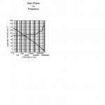
However in the LM4562 data sheet I found a wonderful curve, Phase vs Gain. If accurate this device would do wonders for some types of signal processing. But I think they really meant phase margin.
Attachments
No you are wrong and don't even know it.
Scott,
We already determined you are not in the peanut gallery. So what error do you see?
Scott,
We already determined you are not in the peanut gallery. So what error do you see?
That circuit with the 10 Ohm and 1k Ohm resistor, it works fine there is no problem with NS's or TI's numbers at all.
The term quality has many different definitions to different people. One person might say that a Toyota Camry is their idea of a quality car as it does it job well and stay together for the duration while another person would think anything less than a Mercedes or Porsche is utter garbage for the masses. It is all in your perspective and what qualities you are looking for or must have. John seems to be getting a bit condescending in some of these responses as if he has some secret about what is a quality electronic part here. Perhaps many here do not make their living off designing amplifiers and preamps and such but that does not diminish the fact that many here do seem to understand the differences between components. Sometimes the quality parts are known by many, sometimes by a few, but in this forum that is what is discussed and analyzed to death. Some of this is pure bs and some of this is great information. When it is only for the sake of naming names the information could be construed as biased, but there are times when a particular manufacturer has deservedly earned that reputation for quality. I have no problem taking advise from Scott, or George or Sy or RNMarsh and a handful of others who I can tell by the responses here have a very good idea of what a quality component is and why it is one. John I am sure has had to learn many lessons the hard way just as anyone else does with a lifetime of designing products for themselves or others. Unless you are a chemist I probably know more about polyurethane materials than most anyone on this forum. Does that mean that I have a lock on that information, no, but that is something that I have spent over thirty-five years working with and learning from experience. As long as that information is not going to damage my own personal business I gladly advise others in what I know and how to get the results that others are trying to achieve. I have always thought that giving away your knowledge never hurt anyone, it usually comes back in spades as goodwill and the favor is often reciprocated. I surely don't expect John to print a schematic for something he is working on presently but sharing what switches he prefers and what relays and attenuators would seem trivial in the realm of things, not something that is going to cause someone to change a design based on those simple parts, but just information that could help another while taking nothing away from the supplier of the information.
- Status
- Not open for further replies.
- Home
- Member Areas
- The Lounge
- John Curl's Blowtorch preamplifier part II