I can instantly "ruin" the quality of sound from my system by adjusting how any of the cables are precisely set up within their environment, although nothing in the normal electrical sense has altered one iota. But, what will have been altered is how the materials of the cable and their environment interact.
Incorrect (assuming you are speaking about IC's or PC's)
Any modification of the ground loop path will modify the system. Flux loop trapping is the culprit here, not any material properties of the cables.
As to the micro-diode discussion which I won't quote anyone specific...
A wire inductance is comprised of two parts..the internal inductance which at DC is 15 nH per foot, and the external proximity based inductance, which is typically 160 to 180 nH per foot.
If the interstrand resistance is high, there will be a direct impact on internal inductance up to a total of 30 nh per foot (2 wires). The more oxide, the higher the internal inductance because the orthogonal conductivity is broken.
Also, the more interstrand resistance, the closer to symmetry the internal currents of the wire will be, so external inductance will not change as much vs frequency.
If you suspect a poor oxidised multistrand cable, run a few amperes through it at 20 Khz, and look for high order harmonic hash.
If anybody suspects a cable as doing any bad things as a result of oxide, just test the darn thing. Do an Ls/Rs sweep from 20 hz to half a Mhz..get yourself a 4284A..
Oh, almost forgot...the speaker end zobel? It is good, and a simple consequence of applying t-line theory to a speaker cable.
jn
Richard Marsh and Walt Jung wrote an article on contacts, as I recall, in about 1980, in TAA or was it AUDIO?
We all went into learning mode as to how to make better connections, both permanent and temporary.
Around this time, I recall Apple Computer making a BIG MISTAKE in their product. They made the Apple II computer with a number of gold plated plug-in slots, so that accessories, including extra memory could be added.
Unfortunately they FORGOT to gold plate the plug in board connections, so you had a gold-tin interface. In a relatively short period of time, the connections failed, but the board function could be recovered by just cleaning them and putting them back. Cramolin was first brought out to address problems like this. Later, it was pressed into audio service. I use it on my bench, and have done so for the last 30 years (give or take a couple of years).
Last edited:
Blowtorch schematic
Second hit in Google pictures:
http://www.amplimos.it/images/BLOWTORCH preamp.png


Second hit in Google pictures:
http://www.amplimos.it/images/BLOWTORCH preamp.png
Last edited:
Thanks for this George. Good to see people have been busy while I've been in the bush
I'll get my lawyers to see Yamaha et al for infringing my Powered Integrated Super Sub patents.
The Dynamic Duo are Stan Lipsh*tz & John Vanderkooy, the High Priests of ABX and other good stuff. But their ABX team also have at least one of the best ears in the business.
Positive feedback by current had been used way before. Even Heathkit had tube amp with such thingy implemented, for sale. How it could be patented after that?
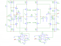
John, what would you think about the added capacitors (parallel to dividers), pl see image.
I am tempted to mention that they are in series with parasitic capacitances of MOSFETs, that means they are in signal path, and their DA will cause reverberation.
thousands and thousands of posts by the so called guru and not one proposal for a diy project for the benefit of our less learned guests !! The excuses are totally absurd
The CTC Blowtorch was a commercial product, not a DIY project.
John Curl isn't build as to assist amateurs with DIY projects.
John isn't obliged to neither publish any schematic, nor to start a DIY project.
There is lot to be learned from John, even when he doesn't start a DIY project and John readily shares his knowledge, though not complete schematics of some of his designs.
Hi PMA
A thought;
Since C-6,5,4,1 etc are in series for noise common to both supplies, and individually on each so they form a capacitive Voltage divider also but with somewhat different ratio than the resistors. (Oscilloscope probes often use a Capacitive divider, two different capacitance's instead of two resistors).
If your inclined (or perhaps sitting in your chair haha), try removing C-6 and 5 (7, 8) and place them from ground to the supplies (ala bypass caps in digital, close, place them close to the R15,16 and c1,4 junction..
This leaves the gates referenced to ground (where the output is referenced) and the divider is now a low pass filter to that reference.
Best,
Tom
John, what would you think about the added capacitors (parallel to dividers), pl see image.
Without Gate stopper resistors, they are very likely to oscillate.
- Status
- Not open for further replies.
- Home
- Member Areas
- The Lounge
- John Curl's Blowtorch preamplifier part II