"The bridge used may not be suitable to survive the fault current, depends on the orientation of the silicon die in the case. If the die are planar to the mounting surface, they may fail open and therefore leave the chassis hot to ground. Note: The potting compound is alumina filled epoxy...the alumina is ground powder and detracts from the tensile strength of the epoxy, but generally does not compromise compressive strength (about 17kpsi). If they are 90 degrees to the mounting surface, the aluminum case will most likely contain the force of the explosion so the silicon will melt into a low resistance mass and then clear the breaker. The bridge "fix" must be reliably capable of failing short, and being able to support fault current long enough to clear a 20 amp breaker magnetically."
Come on! A 35 amp BR can take >200A repetitive and even more non repetitive. If the user gets killed because it fails, it ain't the diode that's the problem, it's the wiring some place else.
Come on! A 35 amp BR can take >200A repetitive and even more non repetitive. If the user gets killed because it fails, it ain't the diode that's the problem, it's the wiring some place else.
What does it take for a 15 or 30 amp house circuit breaker to pop?
Single cycle breakers used to rated for 10,000 amps interrupting, these days lots of folks want 20,000 amps.
(Weird position, we agree!)
")
Last edited:
While you may think we disagree, you've written nothing to support that. Since your argument is unsupported, we clearly agree.
I have not mentioned line sag. What I speak of is entirely independent of that.
Where in code are the 5% numbers you mention. Is it in 2005, 2008, or 2011?
Last I recall, 4% was just a recommendation due to incandescent bulb dimming and what we can see.
j
In all of them, if I have a chance and can find a code book here, may have a chance to get you the section. It is a recommendation that AHJ usually sees as a requirement. A lot of motors don't work at low line voltages (107 is a sure fire killer!) and that gets homeowner complaints, so it becomes a "requirement."
The utility is supposed to be providing 127 to 132 according to current best practice. 117 is still seen and 5% below that is a real problem! (And we both are old enough to remember 110!)
Last edited:
Come on! A 35 amp BR can take >200A repetitive and even more non repetitive. If the user gets killed because it fails, it ain't the diode that's the problem, it's the wiring some place else.
Lets look at an example, one I'm familiar with.The GBPC25 series of bridges.
The peak forward surge superimposed on rated load is 300 amp ONE single half sine pulse, 8.3 milliseconds duration. For 10 cycles, 83 milliseconds, it drops to 150 amps. In this realm of operation, the limit is essentially a heat transport mechanism within the silicon, the heat pulse can't leave the die fast enough. As a result, a part of the area of the die will heat faster and therefore current crowding will occur, blowing the device. If the braze integrity between the silicon and the moly (or tungsten) is perfect, that failure site would be along the outer edge somewhere..but chances are, there will be brazing voids which create internal hotspots.
For fusing (non JEDEC method) within the timeframe of 1 millisecond to 8.3 milliseconds, the GBPC25 is rated at 375 amps^2 times seconds. This is for operation without the rated load superimposed. This number is where the manu basically says the device is toast.
If you review the fault current that can be present at the case, it can go much higher. If you have a 5 foot run of #12AWG romex to the outlet vs a 50 foot run, you will find that the bolted fault calculations at the equipment are quite different. Closer to the panel will be a much higher peak with breaker opening fast, farther away it will be a lower peak but the breaker will hold longer. It isn't possible to state which would be worse for the integrity of the bridge as a result of the complexity of the problem. Note that the early bolted fault calculations for arc flash have been revisited because bolted fault is not really worst case in all scenarios.
Square D has the time curves on their site. They show clearly the thermal area as well as the magnetic one.What does it take for a 15 or 30 amp house circuit breaker to pop?
10k is a typical maximum fault requirement for some breakers. It is the number that the breaker must be capable of without containment breach.Single cycle breakers used to rated for 10,000 amps interrupting, these days lots of folks want 20,000 amps.
(Weird position, we agree!)
j
Last edited:
In all of them, if I have a chance and can find a code book here, may have a chance to get you the section. It is a recommendation that AHJ usually sees as a requirement. A lot of motors don't work at low line voltages (107 is a sure fire killer!) and that gets homeowner complaints, so it becomes a "requirement."
The utility is supposed to be providing 127 to 132 according to current best practice. 117 is still seen and 5% below that is a real problem! (And we both are old enough to remember 110!)
In some cases, what is deemed "code" is a matter of interpretation of the AHJ. Only in weird instances is it necessary to take a disagreement to the committee. Try building a DC machine in a controlled environment and in a tunnel..sheesh..
j
Thanks KBK for the 'fortitude' to follow through with your explanation as to why your cables are different in character than typical wires.
This topic has also invoked a number of 'links' that have been useful in picking up new ideas and actual facts that I personally had not noted previously.
For example 'Brown's Gas' and its explanation as to why it might be 'special' is now 'obvious' once it is explained, even casually.
Also, I now have on my computer Vol 3 of Heaviside's book. Thanks, whoever put that up.
Personally, I get more from the 'links' people here post, than almost any conventional argument made here.
Last edited:
What does it take for a 15 or 30 amp house circuit breaker to pop?
I found the sheet. It's from the Schneider webpage. doc 730-4.
At 9 times rated current, the breaker must clear in 1 second. So, 20 amp breaker, 180 amps for one second.
400 amps, 280 milliseconds.
800 amps, 70 milliseconds.
1000 amps, 50 milliseconds.
Those are numbers that can rupture a bridge.
At three times rating, 60 amps...the breaker must not trip before 2.5 seconds, but must trip within 10 seconds.
So, bottom line....circuit breakers are not designed to save silicon. Circuit breakers are only there to protect the wires.
j
In some cases, what is deemed "code" is a matter of interpretation of the AHJ. Only in weird instances is it necessary to take a disagreement to the committee. Try building a DC machine in a controlled environment and in a tunnel..sheesh..
j
My practice is to sit down with the AHJ before I begin a project and give him a copy of the wire system data sheets and list of the applicable code sections. They generally get the hint I have done this specialty work before and understand the code. That allows them to leave me alone and spend their time on folks who have never seen systems of the scale of what is going on.
Interestingly enough they all seem to remember me, even years later.
I did the same drill when I started renovating my house. The electical inspector tried to look like everyone gives him a submittal with all of the data sheets on a regular basis! It was a bit weird because I don't really design or install residential wiring and some of the code has changed. He reviewed what he expects, which was GFI or ARC interrupting on every outlet except the drier and outlets with built in plastic connection guards. So I guess the electricity did used to leak out of the old style outlets.
As to current faults into a chassis, the breaker rating although nice may not really be the issue! It is the safety ground that has the diodes inserted. So although the fault current may be through the breakered hot line I have seen exploded 10,000 amp breakers (apparently so have others which is why 20,000 amps is becoming the rule) there can be more than that in a fault!
Then there is the possibility that it is an ungrounded neutral to safety ground fault. At the code permitted unbalance of 6 volts this should be under 100 amps. But if it is an incorrectly wired neutral then it would be at least a 100 amp or larger main feed breaker and 10,000 amps or more could occur!
I really prefer double insulated. It not only is safer, but it helps reduce that line noise you keep pretending doesn't exist! (
)My method is to use a safety ground to the power transformer mounting. The mounting is of course well insulated (10KV typical) from the chassis. That way a fault should still trip the protection circuits. As a backup a fuse having a rating 1.5 x the back panel fuse, is also mounted with the transformer. I have seen silly folks who fuse the line and the neutral, not understanding a neutral fuse failure is a bad thing.
Better use a ground fault circuit interrupter for that job. It's also not meant for protecting silicone (well....) but it will already trigger at 30mA leakage (at least the types we use, it is mandatory here), therefore it will start triggering at the very beginning of a fault. The fast ones (i.e. not those who are arbitrarily slow, up to 250ms) AFAIK will break at 50ms as long as the fault current is around 150mA.
Scott,
Can you point me to some of these sites? Monday is a good day for humor.
BTY folks actually have made unicorns out of horses by adding cells to grow a single horn! (And you though folks here had too much time on their hands!)
Blacklight Power - Wikipedia, the free encyclopedia
Transmutation
Steorn - Wikipedia, the free encyclopedia
And of course Google Tom Bearden the godfather of free energy hoaxing.
1000 amps, 50 milliseconds.
20A curve reads 18ms for the 50 x current rating. (still a lot)
20A curve reads 18ms for the 50 x current rating. (still a lot)
Thank you for the correction. I accidentally used the 15 amp line...my mistake...
cheers, j
Just doing my homework, Mr John.
(tried to read the collected works of Mr Heaviside, but developed prosaic writer's rash after the first 100 pages)
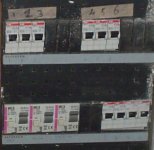
Image of the electrical panel in my home (barn and swimmingpool have a separate board)
16A circuit breakers, each group ( 2 of 3, 1 of 4) connected to a ground fault circuit interrupter (bottom left, 30mA types )
(tried to read the collected works of Mr Heaviside, but developed prosaic writer's rash after the first 100 pages)
Image of the electrical panel in my home (barn and swimmingpool have a separate board)
16A circuit breakers, each group ( 2 of 3, 1 of 4) connected to a ground fault circuit interrupter (bottom left, 30mA types )
Attachments
Last edited:
Just doing my homework, Mr John.
(tried to read the collected works of Mr Heaviside, but developed prosaic writer's rash after the first 100 pages)
Ya got an "A"..
j
Blacklight Power - Wikipedia, the free encyclopedia
Transmutation
Steorn - Wikipedia, the free encyclopedia
And of course Google Tom Bearden the godfather of free energy hoaxing.
Thanks Scott,
The first one provides to me an iron clad argument for raising taxes on capital gains, as it proves there is too much loose investment capital. Either that or they should invest in gold which can be transmuted into brokers' pocket change.
The second one says not to download it (among other things) without the authors permission. So of course I didn't read it. But by my physic properties I loved the bit about reverse winding a voice coil so that it has no magnetic field, but can remove radioactivity instead!
Now the third was on the magnetic perpetual motion machine. That one pops up fairly often. Of course it is possible to make a magnet perpetual motion machine. When I get around to it I will give you the details!
Thanks for the Monday smile.
Just doing my homework, Mr John.
(tried to read the collected works of Mr Heaviside, but developed prosaic writer's rash after the first 100 pages)
Although I seem to be retarded compared to you (only 25 pages sofar) and being used to enjoy old style engineering writing, I can’t help asking:
Is there anything that I read in the first (Volume I, Chapter I, Introduction)17 pages that does not match the subject of questionmarks, unknowns, and the debates due to technical attitude differences present in this thread?
I have 2 beers and a few cigarettes so far but I still ask myself: What the heck?
(Jneutron, you are in there. Page 2, para 2 )
George
(Jneutron, you are in there. Page 2, para 2 )
George
Nobody's ever called me practical before....
sniff...now I feel wanted....
good one...
j
John (N),
Just for you.... http://www.diyaudio.com/forums/diya...udio-component-grounding-interconnection.html
ES
Just for you.... http://www.diyaudio.com/forums/diya...udio-component-grounding-interconnection.html
ES
the godfather of free energy hoaxing.
strange how a hoax could get a patent
Patent US6362718 - Motionless electromagnetic generator - Google Patents
and -
for those of you that worship at the altar of the skeptics religion,
here is something else to ad to your (fervent) devotion -
(and please,
become as hysterical as you possibly can,
some one might use all that free energy,
to destroy the universe!)
(~ignoring of course what happened the last time~)
http://www.youtube.com/watch?v=pZb05BaRmqU
6000 rpm magnet motor MOVIE MECSDGP REPOST.wmv - YouTube
Last edited:
- Status
- Not open for further replies.
- Home
- Member Areas
- The Lounge
- John Curl's Blowtorch preamplifier part II