Hi,
How do you sugest to improve Le(i), Re(i) and BL(i)?
Ciao T
much more can be gained by making the driver better, than trying to correct the errors they are born with
How do you sugest to improve Le(i), Re(i) and BL(i)?
Ciao T
I have got a question from "subjective" domain.
Usually we consider interaction between driver stage and output stage (lets suppose both are MOSFETs) in terms of driver stage output impedance (usually resistance R) and gate capacitances of the output stage (some C).
Usually it is supposed, that if in two different designs the RC is close, hence the stage interaction issue is solved similarly.
What I observed subjectively, from listening, one never get similar sound in case if gate capacitances of output stage differ strongly, lets say as 100pF and 1000pF. For the second case, by simply decreasing driver stage output impedance, we could hardly approach the sound at the first case. I suppose, there could be some second order effects, related to interaction of stages. Are there any ideas, what kind of effects could play here?
I second Joachim,,, much more can be gained by making the driver better, than trying to correct the errors they are born with, besides any driver that has mechanical damping cant be reversed, as its components are neither linear or amplitude consistent...
Exactly, so, Thorsten, that is why you want drivers with the highest possible Qms. Any mechanical dampening that is not there cannot cause problems. All mechanical dampening that is will.
vac
Thorsten, this is just one one the things i recently did on one of my drivers, Increased bl to 2 dB more sensetivity while l maintained Re and reduced Le so much that impecance had just risen to 7,5 ohms at 10 KHz (5,6 ohmmDCR) where it was 15 ohms prior, imagine what that did to performance, but mechanical damping is also what goes on in a mambrane Mwhere it totaly unpridictable and varies with SPL.
Le is horrendous besause it varies up to 50 % vith excurtion amplitude. So getting that out of the driver improves performance quite a bit, maybe not on the direct liniarty/responce of the driver, but for sure when you make it into a system
Le is horrendous besause it varies up to 50 % vith excurtion amplitude. So getting that out of the driver improves performance quite a bit, maybe not on the direct liniarty/responce of the driver, but for sure when you make it into a system
Hi,
Proof?
Given the extent of nonllinearity in electrical damping I am not sure mechanical damping done right (e.g. flowresistance integrated in basket) would do so badly by comparison.
Ciao T
Exactly, so, Thorsten, that is why you want drivers with the highest possible Qms. Any mechanical dampening that is not there cannot cause problems. All mechanical dampening that is will.
Proof?
Given the extent of nonllinearity in electrical damping I am not sure mechanical damping done right (e.g. flowresistance integrated in basket) would do so badly by comparison.
Ciao T
I have got a question from "subjective" domain.
Usually we consider interaction between driver stage and output stage (lets suppose both are MOSFETs) in terms of driver stage output impedance (usually resistance R) and gate capacitances of the output stage (some C).
Usually it is supposed, that if in two different designs the RC is close, hence the stage interaction issue is solved similarly.
What I observed subjectively, from listening, one never get similar sound in case if gate capacitances of output stage differ strongly, lets say as 100pF and 1000pF. For the second case, by simply decreasing driver stage output impedance, we could hardly approach the sound at the first case. I suppose, there could be some second order effects, related to interaction of stages. Are there any ideas, what kind of effects could play here?
Could it have any ground an idea, that driver stage Rout - L of wiring - C of gate(s) start to interplay ? For the same L, with larger C and smaller Rout we could allow achieving some ringing conditions at close to or below 100MHz frequencies, that are already recognizable by most active parts.
In case of tube schematics, we usually deal with high Rout and very small C (like few pF).
That is correct, I question the reversibility of loudspeakers to the degree of getting any useful results, and I don't see any use for doing it with two.
Scott,
We both are looking for the same thing, an easy way to get accurate acoustic measurement results. I have looked at two ways, a hot wire signal source and using loudspeakers bi directionally.
Reciprocity refers to a reciprocal relationship. The microphone standard uses three as a minimum, as it is intended to give converging results. I don't think that is required for a simple is it flat question. It is if you want to know how flat!
As to NIST traceability accuracy that is what a pistonphone and barometer are for. My acoustic standards are better than many local testing labs! That is needed as sound level meter calibrators need to be checked each year. SLM's are checked before each use. The cheapies can drift by several db between uses and operating temperature. The local noise ordinance allows for 5 db calibration error!
ES
Flow resistance is equally bad. As it is prone to reflections and turbulence which is both unpredictable and impossible to model...At Raidho this has been one of the key drivers to design our magnet structure, which has very litlle compression and reflection from the rear structures in the driver.
http://www.raidho.dk/uploads/Raidho-Acoustics-Ribbon-Ceramix-Drivers.pdf
http://www.raidho.dk/uploads/Raidho-Acoustics-Ribbon-Ceramix-Drivers.pdf
Reciprocity refers to a reciprocal relationship. The microphone standard uses three as a minimum, as it is intended to give converging results. I don't think that is required for a simple is it flat question. It is if you want to know how flat!
I recently bought 32 cheap Karaoke microphones, going to order a pair of enclosures in Tap Plastics for 16 capsules each, arranged as line arrays. Let's check how Karaokish will they sound driven by transformerless tube outputs.
")
I recently bought 32 cheap Karaoke microphones, going to order a pair of enclosures in Tap Plastics for 16 capsules each, arranged as line arrays. Let's check how Karaokish will they sound driven by transformerless tube outputs.
Thank You Thank You Thank You That means there will now be 32 less chances for Karaoke now!!!
Thank You Thank You Thank You That means there will now be 32 less chances for Karaoke now!!!
It depends on reciprocity. Don't you expect to hear a choir of 32 Karaoke singers?
My last post to the idea of current drive of a dynamic speaker. 1st plot shows impedance plot vs. frequency calculated from the equivalent diagram shown. The 2nd plot shows transfer function of this equivalent speaker circuit with increasing voice coil resistance as a parameter (higher resistance = closer to current drive). We can see that when increasing voice coil resistance, i.e. approaching to current drive condition, the only thing we get is a resonance peak at bass frequencies and decreasing efficiency. Exactly as expected.
Those curves look like they could be used for a "loudness control" feature
Scott,
As to NIST traceability accuracy that is what a pistonphone and barometer are for. My acoustic standards are better than many local testing labs! That is needed as sound level meter calibrators need to be checked each year. SLM's are checked before each use. The cheapies can drift by several db between uses and operating temperature. The local noise ordinance allows for 5 db calibration error!
ES
Pistonphones are only absolute SPL at one frequency. I repeat I'm trying give the average DIY'er something they can build for a few bucks and spare parts that gets close enough for DIY. BTW the medical pressure transducers are extremely stable as barometers -3dB equals

I just spoke to Jack Bybee today. He was complaining that one of the front tires on his Mercedes started to disintegrate while he was driving, after only 10,000 mi. I asked him if there was something wrong with the car, but he said no, it has to do with the variable suspension, he was told. I'm glad that I don't drive that car, I could not afford the tires. '-) For the record, he won't be at CES this year, he just don't want to exert the effort, and I don't blame him. As we get older, it is harder and harder to do CES. My office partner, Brian Cheney of VMPS will be there, however, showing with Jim Bongorno (sp) which should be interesting.
Those curves look like they could be used for a "loudness control" feature
The effect of amplifiers with high output impedance - of many tube amps.
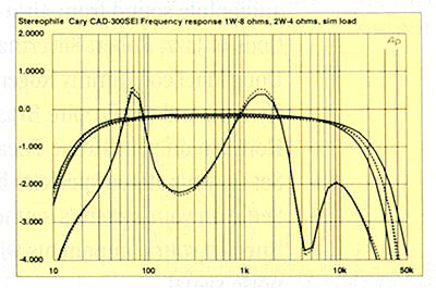
http://www.stereophile.com/content/cary-audio-design-cad-300sei-integrated-amplifier-measurements
Last edited:
PMA, you exaggerate the effects of tube amps on being a tone control. Yes, the frequency response will change somewhat, but it might even get better, rather than worse. I am now perhaps driving my WATT's with 0.5 ohms, at least, and it sounds just fine. This is a damping factor of about 10. My Dyna tube amps have a damping factor of 15, so why exaggerate the problem? You did the same with current drive. Who is to say that current drive, IN SOME CIRCUMSTANCES, isn't better? Your experience curve is fairly limited, as I found this out almost 50 years ago.
Pistonphones are only absolute SPL at one frequency.
Actually, no. They are accurate across the range they work across, usually not much above 350 Hz, or you get the equivalent of valve float. Since a pistonphone is a very constant known displacement transducer the pressure is constant (or so the manual says, with instructions for doing just this).
A few other comments-
Quad used the cancellation trick in the factory floor for QA of the ESL63 from the beginning. It works really well and its easy, but not face to face. Two side by side out of phase will get a really good sharp null if they are working right.
Reciprocity calibration is nice for national labs but not too practical for anything else. The measurement mikes are normally done with an electrostatic process with a special screen that fits on the mike to drive it. Works well but won't work with the Panasonic. Also opens up the can of worms between pressure and free field microphones. Fortunately, B&K supply correction curves that permit moving from one mode to the other in effect.
The Earthworks guys were pretty forthcoming on their spark testing and indicated that the 1/4" Microtech Gefell was the most accurate transducer they have tested. They got quiet when I started asking about the mechanical arrangements.
I'm very interested in the spark calibration method. My concern is that the energy at low frequencies is so low that there will be little useful information but I would be happy to explore it. I have a large collection of measurement microphones as well but the Girardin (Panasonic) mikes that come with Praxis make everything too easy so they don't see much use.
I have been using ground plane measurements time windowed in a basketball court in the warehouse very effectively. No reflections for more than 50 mS gives very good low frequency extension to the measurements. It even works when the crusher is running at the other end of the warehouse.
- Status
- Not open for further replies.
- Home
- Member Areas
- The Lounge
- John Curl's Blowtorch preamplifier part II