Probably. And there is only one way to find out.
And that is always the difficult bit
")
Added complexity ?
What is the benefit, assuming most opamps has good PSRR ?
It was an answer on your question about idle current and it's thermal stability.
Wavebourn, you should stick to what circuits you know to defend or criticize them. You are speculating without trying.
Now let me ask you something: Would you still recommend using the AD823 and the AD795 for your design. Did you just 'liberate' these devices from your former employer? They make no rational sense, one is a dual, the other is current starved.
I wrote all about opamps, even added a picture of the one that I used.
And explained, that just selected from LTspice library some almost random opamps because could not find a "generic" opamp there. What AD823 in USSR back in 1977?
John, please read what I explained, before asking questions.
Wavebourn, you should stick to what circuits you know to defend or criticize them. You are speculating without trying.
Speculating?!
It is called Analysing obvious things like all over the map idle current of output transistors and all technological dirty currents from opamp to bases of transistors in addition to currents through output transistors. It is obvious, John!
Do you need, John Curl, to measure dependence of beta on temperature before understanding it; do you have to try every time?
I am speechless...
Last edited:
. Did you just 'liberate' these devices from your former employer?
What employer back in 1977? You forgot that I graduated in 1981?
Time to read historic books, John! About PIM, etc...
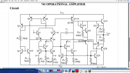
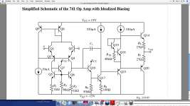
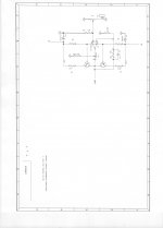
Do you still remember what PIM means? Everyone, let us presume that Wavebourn has found something important about IC's. Let's then look at a schematic of a typical IC op amp, in fact the very IC that my amp design was first used in. I have put up both the exact (hopefully) and the simplified schematic of the uA741, one of the most successful amp topologies in history, and the most studied IC op amp topology (in general) at university. Certainly it was when I attended class. Now let us look for 'technological dirty currents' from the op amp. Can you find any? All that I see is current sources or average summed loads, except for the output stage. What about the rest of you. See anything that I missed?
Attachments
Reminds me of an interview I had ones. The guy interviewing me said: "I see you worked on the diode pumped laser, I got my PhD in china on it. What do you know about it?" Me: "We invented it"
I did not know that JC invented 741. Wow !

Now let us look for 'technological dirty currents' from the op amp. Can you find any? All that I see is current sources or average summed loads, except for the output stage. What about the rest of you. See anything that I missed?
Yes, not much in 741, still common mode currents in LTP and differential in VAS. In the opamp they are there to make transfer function from input to output cleaner by contaminating rails. Not vice verse.
If current sources and other devices are ideal, why would we be still here?
Now, tell us more please about your customer who drives his horns by such an amp. What is it's output power? What is idle current? How many times it changes with only 30 degrees C increase of temperature?
Last edited:
No, I did not design the uA741, but I came close. When you were still a kid, (1966) I was in charge of analyzing the uA709, and when you were a little older (1969) I was designing uA741's into video servos at Ampex Research. Within a year later, I had made this simple little circuit using the uA741 and a couple of plastic T0-220 power transistors for a road trip, driving a PA monitor composed of a JBL D130F woofer and an 075 tweeter (as I recall) driven by a Nagra recorder and protection mastering tape recordings that my company (Alembic) had made recently. I ran it off the bus (we were camped out in) battery, and it worked pretty darn well. Later, I took the same amp, and added a +/- 15V supply and drove a K-horn in my home system. I guess I must be deaf, because while not perfect, it sounded OK.
This is not a perfect design, just a simple, fairly elegant one, instead. It will not work at very high voltage easily, partially because it has no thermal compensation, but IF you can stand to operate with an Iq of 200-500ma, it works great, and is much faster than the IC's slew limit, and smooth sounding.
The earlier circuit (cheap power amp) that I originally put up adds bias setting resistors that can lower the Iq to anything you want, but I never could get it to sound nearly as good as it was in the Class A mode. Too much Xover distortion, probably.
Attachments
Last edited:
As I suggested before, it can be thermal compensated by using current mirrors instead of loading on naked bases. You can run them in class A then, but now under control. Current mirror ratios also would define currents when output is shorted, if opamps have output current limiting.
Such inputs were common in PA amplifiers before class D took over. And for higher swing opamps were connected through Zeners in series.
Such inputs were common in PA amplifiers before class D took over. And for higher swing opamps were connected through Zeners in series.
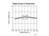
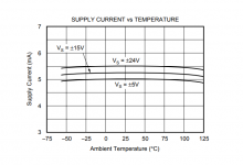
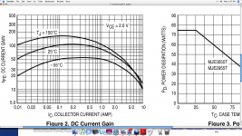
Another factor that keeps the current driven output devices from getting out of hand is the way the beta changes with temperature. Above a certain current (Iq) higher temperature tends to push the beta change closer to the 25 degree C rating. For example:
Attachments
By the way, if any of you want to get an understanding as to how really old I am: Just watch the movie: 'Hidden Figures' now out on HBO. Yes I ran the IBM 7090-94 back in 1963. That is the computer in the picture under my name on this website. I already had 3 years of college under my belt at the time (engineering-physics) and served about a year as an electrical technician at UL.
By the way, if any of you want to get an understanding as to how really old I am: Just watch the movie: 'Hidden Figures' now out on HBO. Yes I ran the IBM 7090-94 back in 1963. That is the computer in the picture under my name on this website. I already had 3 years of college under my belt at the time (engineering-physics) and served about a year as an electrical technician at UL.
It is great John that you are still in such a good form!
By the way, my father in law is almost 93, and couple of years ago he completed a course of quantum physics that he missed back in an university. ;-)
When temperature increases beta goes up increasing current that increases temperature.
With current mirrors, you can make a thermal contact and compensate this current change.
Now I see what you are getting at.
Thx for the hint,
Patrick
- Status
- Not open for further replies.
- Home
- Member Areas
- The Lounge
- John Curl's Blowtorch preamplifier part II