Modern ones all sample both channels at the same time. See example below.Are there audio AD converters that sample L and R coincidently before transferring the L and R data into serial data stream ?.
Attachments
Which is why I asked if you did the test. You said yes, so can you post the results?
Thanks,
John
I am sorry but that was all done 10+ years ago. It would take too much time to find the data and or redo some of it. And, it would not give any more illumination regarding ground-loop source and solution.
I also have a Fluke 43B, and instruments which seperate the DM and the CMode voltage and measures the amplitude of each on the ac line.
THx-RNMarsh
Thanks.Modern ones all sample both channels at the same time. See example below.
That would depend on the DA converters used, and not software if one only DA chip is used.For a while some of the sound blaster cards and USB interfaces output the L and R channels staggered -- the L led the R by one sample. I think it got fixed in later drivers (but not sure).
Most consumer CD players used multiplexed DA converters.
My question is mainly concerning AD capture.
The first CDs were mastered on Sony PCM-1610 and PCM-1630.
I cannot find schematic for the 1610, but the 1630 used CXA20018/CXA144S Multiplexed AD converter.
Dan.
I'm often amazed at the hyped complaints or fears - do the sound propagation in air path length and tell me if you speakers-listening position are located that precisely
I use a laser interferometer to position mine

The bigger problem is holding my head still...
Thanks.
That would depend on the DA converters used, and not software if one only DA chip is used.
Most consumer CD players used multiplexed DA converters.
My question is mainly concerning AD capture.
The first CDs were mastered on Sony PCM-1610 and PCM-1630.
I cannot find schematic for the 1610, but the 1630 used CXA20018/CXA144S Multiplexed AD converter.
Dan.
The tracks on the very first Sony test disks were coincident, don't remember the copyright date (82-84?). FR anomalies in sum and difference of the channels should easily tell.
FR anomalies in sum and difference of the channels should easily tell
yes you get 1st order digital filtering of the mathematically combined mono content
but Listening to Stereo is not summing and differencing, I really don't expect/recall hearing the apparently feared massively audible frequency response variation from say one speaker being 1/3" closer/farther in a 6-10 foot Stereo triangle setup in a room
the mixing/mastering delay between channels would be expected to be a small image shift - and only in recent DAW has that delay manipulation become common in spatial modeling processing plugins
most commercial music was produced with "image" "painted on" with cruder relative amplitude pan potting
Human hearing is remarkably adaptable. Toole's recent AES paper makes the point that two ears and a brain are essential, and one microphone at a listening position is woefully inadequate. Yet the latter is what the majority of room correction schemes attempt to use to derive their settings.
For those of us without the pre-requesite stack of instrumentation is there a (within forum rules) DIY friendly CM/DM measurement method out there.
Depends of the frequency you are interested in.
Basically you will need some kind of spectrum analyzer.
Common mode noise can be measured as the sum of all currents through the cable using an isolated current probe.
This common mode probe can be built based on a high u ferrite/nanocrystalline or amorphous toroid core. Wind 50 turns of enamelled wire, terminate with 50 Ohms and you have a wideband current probe that delivers 1V/1A.
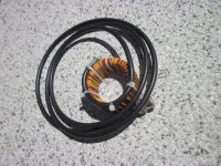
This is my DIY current probe using a VAC core, operating in the range of 20Hz ~ 20MHz approx.
Attachments
Human hearing is remarkably adaptable. Toole's recent AES paper makes the point that two ears and a brain are essential, and one microphone at a listening position is woefully inadequate. Yet the latter is what the majority of room correction schemes attempt to use to derive their settings.
Seems reasonable to me. We would't want a stereo record recorded with only one central mike, would we? So how can it work with only one in sensoring the rom, but we need a minimum of two for a stereo recording?
For a while some of the soundbaster cards and USB interfaces output the L and R channels staggered -- the L led the R by one sample. I think it got fixed in later drivers (but not sure).
I can certainly concur with that statement, as it was happening with my SB card.
It was a very interesting listening issue as a result. In headphones, it was necessary to move the pan control to one side a bit in order to center the image. The problem was, humans have a frequency dependent panning sensitivity, so different frequencies required different panning shifts to center that aspect of the image to counter the interaural time shift.
I spent a lot of time listening to that, trying various experiments to see what was happening. So, I backed into what the card was doing from the listening standpoint.
If I drove speakers from the output, it didn't matter, that kind of time delay fixation would require the ol vice on the head...
John
For those of us without the pre-requesite stack of instrumentation is there a (within forum rules) DIY friendly CM/DM measurement method out there.
Yes, massive quantities of test equipment is useful for all manner of curious things. But not needed for your CM-DM testing:
Ok.... here is a cheap and easy way --- take a tube filament transformer step down to 12.6vac. In USA, using a 120v to 12v gives a convenient 10:1 ratio and the BW is more than adequate for audio freqs.
In series with the primary, place a 10 Ohm 1/2-1W resistor and in series also a .01mfd cap of appropriate voltage rating. That will cut the line freq out of the measurement. But the exact value can be tested for and adjusted to suit your transformer. Using the two primary wires as probes, going between H and N will give you "Normal Mode" (DM) and placing the primary probe wires between ground and neutral will measure CM noise as seen on the secondary (X10). The secondary wires can go to a scope or spectrum analyzer.
Or you can buy this in a box..... from PowerVar. Model: Power Probe 115. It is yet another one of my test tools.
THx-RNMarsh
Last edited:
Seems reasonable to me. We would't want a stereo record recorded with only one central mike, would we? So how can it work with only one in sensoring the rom, but we need a minimum of two for a stereo recording?
Cowboy Junkies - Trinity Sessions
I would expect the test discs to be coincident.The tracks on the very first Sony test disks were coincident, don't remember the copyright date (82-84?). FR anomalies in sum and difference of the channels should easily tell.
Good idea re cancellation, thanks.
Dan.
Ok.... here is a cheap and easy way --- take a tube filament transformer step down to 12.6vac. In USA, using a 120v to 12v gives a convenient 10:1 ratio and the BW is more than adequate for audio freqs.
In series with the primary, place a 10 Ohm 1/2-1W resistor and in series also a .01mfd cap of appropriate voltage rating. That will cut the line freq out of the measurement. But the exact value can be tested for and adjusted to suit your transformer. Using the two primary wires as probes, going between H and N will give you "Normal Mode" (DM) and placing the primary probe wires between ground and neutral will measure CM noise as seen on the secondary (X10). The secondary wires can go to a scope or spectrum analyzer.
Or you can buy this in a box..... from PowerVar. Model: Power Probe 115. It is yet another one of my test tools.
THx-RNMarsh
That is simpler than I was imagining, which was an arrangement of current probes in a box. Put an IEC input and flying lead out and could go in line with whatever UUT you were looking at. Calibration above 50KHz tricky without RF gear, but I do have access to that if I go and pick it up.
Certainly worth a play.
.......and the balance control still didn't fix the problem !.I can certainly concur with that statement, as it was happening with my SB card.
It was a very interesting listening issue as a result. In headphones, it was necessary to move the pan control to one side a bit in order to center the image. The problem was, humans have a frequency dependent panning sensitivity, so different frequencies required different panning shifts to center that aspect of the image to counter the interaural time shift.
I spent a lot of time listening to that, trying various experiments to see what was happening. So, I backed into what the card was doing from the listening standpoint.
If I drove speakers from the output, it didn't matter, that kind of time delay fixation would require the ol vice on the head...
John
I fine adjust tape azimuth by listening for image centering and consciously ignore slight channel level/fr difference, so I have trained myself to hear/notice phase errors.
In my work tractor I have speakers mounted and angled directly at each earole, distance 20” each side.....big headphones !.
I play tracks from a thumb drive and some recordings sound not quite right.
Placing my filters on the USB extension cable tightens imaging and makes positioning dramatically more aparrent...... very interestingly.
Dan.
- Status
- Not open for further replies.
- Home
- Member Areas
- The Lounge
- John Curl's Blowtorch preamplifier part II