Moi?
I have nothing against the resistively (over)damped approach, just concerned about the need for knowing the inductance, which as mentioned could be determined automatically, but would be "out of the way" in normal operation.
I had always assumed (perhaps wrongly) that you need a test record to set up a cartridge properly and as such you could infer the inductance from the high frequency response. If you don't have that capability agree you need data.
The loading resistance would be the synthetic "cooled termination" (using the preamp's own gain for best results---see van de Gevel again for a discussion and his particular implementation).
will have to take a look at that article.
Amusing seeing bragging about .3% distortion. Interesting also is that there is a non trivial difference between channels. From what I see here the difference between the fussiest and average casual setup spans all of -40 to -50dB.
No, when I run spot harmonic distortion checks at 1kHz (a la VdH, at similar levels), I obtain significant differences between say a OM40 (FG) and a Stanton 500 (spherical) as follows :From what I see here the difference between the fussiest and average casual setup spans all of -40 to -50dB.
OM40 : 2nd -51.6dB; 3rd -51.8dB; 4th -69.1dB
S500 : 2nd -18.9dB; 3rd -24.7dB; 4th -48.3dB
So there should be a very observable significant difference between 'average casual' and 'fussiest' setups IME.
I agree that those VdH published figures seem unremarkable IMO, and that's being kind............
You'll see the effects of the MM/MI inductance but convolved with the mechanical resonances, so no direct inductance data. For most MC otoh the L is tiny, and except for the radical approach of negative conductance loading, is too small to do the 75us tau. Even the time constant with a low-Z summing node is going to be small.I had always assumed (perhaps wrongly) that you need a test record to set up a cartridge properly and as such you could infer the inductance from the high frequency response. If you don't have that capability agree you need data.
I guess I like to start with the manufacturer's recommendations for loading and see how it sounds. If one is pursuing the overdamped input then that adds another variable, and knowing the inductance and internal resistance is crucial.
I've never seen that tabulated or discussed. One supposes that the control over the number of turns is tight, but the effect of the ferromagnetic material is dominant.Any idea how large the L spread would be within a certain cartridge type?
Jan
However I was told by Geren at Cinemag that it's hard to get good copper wire these days!
@scott That said, a bracket of 10dB probably covers most premium cartridges, if that is what you meant...........but these aren't really 'average casual setups' methinks.
Sure you know, but just in case check out Paul Miller's Miller Audio Avtech resources which hosts his test result reports for most current cartridges. He tests at 5cm/s 1kHz spot, and perhaps a median thd figure is c -30dB, ie about 3% or so.
Miller Audio Research
Sure you know, but just in case check out Paul Miller's Miller Audio Avtech resources which hosts his test result reports for most current cartridges. He tests at 5cm/s 1kHz spot, and perhaps a median thd figure is c -30dB, ie about 3% or so.
Miller Audio Research
No, when I run spot harmonic distortion checks at 1kHz (a la VdH, at similar levels), I obtain significant differences between say a OM40 (FG) and a Stanton 500 (spherical) as follows :
OM40 : 2nd -51.6dB; 3rd -51.8dB; 4th -69.1dB
S500 : 2nd -18.9dB; 3rd -24.7dB; 4th -48.3dB
So there should be a very observable significant difference between 'average casual' and 'fussiest' setups IME.
I agree that those VdH published figures seem unremarkable IMO, and that's being kind............
Sorry I was talking about care in setup all else being equal. Even so Jan's numbers never went to -18.9dB, even a (formerly) 15$ Grado does ~-38db 2nds on my well used STR100. Were you around when we discussed the cutting lathes with compensation for spherical stylii built in?
Last edited:
IIRC There is a guy David Laloum who used to post on forums a few years back who seemed to collect hundreds of MM carts and habitually measured their inductance and resistance, considering it a figure of merit if they were closely matched. He posted loads of results, but I'm working from memory and could be wrong, but would say that the vast majority were within +/- 10% of published spec, and that it was common to find perhaps up to 5% variance between channels. Actually it seems the winding method isn't always closely controlled, and so wire length versus number of turns commonly varies. Precision is not a word that springs to mind, but sufficient for the purpose no doubt.I've never seen that tabulated or discussed. One supposes that the control over the number of turns is tight, but the effect of the ferromagnetic material is dominant.
Perhaps David's posts are archived or he still posts, but if you want to know definitively he is certainly the man.
Yes, it's the worst I've measured at 1.2 cm/s, and could be defective I suspect, but it was new..........Even so Jan's numbers never went to -18.9dB
At 5cm/s -25dB readily achievable by some carts. Test level, location on the record and whether 33 or 45rpm can make a major difference and means results can be hard to compare.
There is no date on this link that I saw but he does have a fair amount of material that comes up in a search.IIRC There is a guy David Laloum who used to post on forums a few years back who seemed to collect hundreds of MM carts and habitually measured their inductance and resistance, considering it a figure of merit if they were closely matched. He posted loads of results, but I'm working from memory and could be wrong, but would say that the vast majority were within +/- 10% of published spec, and that it was common to find perhaps up to 5% variance between channels. Actually it seems the winding method isn't always closely controlled, and so wire length versus number of turns commonly varies. Precision is not a word that springs to mind, but sufficient for the purpose no doubt.
Perhaps David's posts are archived or he still posts, but if you want to know definitively he is certainly the man.
https://sites.google.com/site/zevaudio/turt/cartridge-comparison-list
Thanks for that information.
Yes, it's the worst I've measured at 1.2 cm/s, and could be defective I suspect, but it was new..........
At 5cm/s -25dB readily achievable by some carts. Test level, location on the record and whether 33 or 45rpm can make a major difference and means results can be hard to compare.
This is a better one from my measurements - still no match for a crappy $50 class D amp, to just mention something ;-)
The xtalk graph is interesting - equal xtalk L>R and R>L is at 1 degree angle of the cart, but lowest is at about 1/3 degree angle. Question is: how is this related to the actual angle of the stylus? 1 degree difference between vertical stylus and horizontal top of cart body seems not unreasonable but it does mean that leveling the cart body in the hope to set the stylus exactly vertical is not always good.
Jan
Attachments
Last edited:
But this genuinely presents fresh preamp topology opportunities.
Everything old is new again.
")
The xtalk graph is interesting - equal xtalk L>R and R>L is at 1 degree angle of the cart, but lowest is at about 1/3 degree angle. Question is: how is this related to the actual angle of the stylus? 1 degree difference between vertical stylus and horizontal top of cart body seems not unreasonable but it does mean that leveling the cart body in the hope to set the stylus exactly vertical is not always good.
Jan
You can't be sure that the internal L & R are perfectly perpendicular (or that the cutter head is perfect). 1 degree off of perfect is like a 1% error on something that is not easy to do close tolerance. You have several pieces all adding their own errors- stylus to shank shank centering on coils (magnet or iron in MM case) field alignment to moving parts, impact of tracking alignment etc. And so very hard to get right. I would get the mechanical alignment dialed in for min crosstalk (reproduce axis best aligned with record axis) and then use DSP to get the eq, response etc. including crosstalk optimized. It seems the lower limit on distortion is about -50 dB (.3%). Getting less may be a distortion cancelling effect that could actually be adding stuff. Looking at all the variables its clear why phono stuff is so tuneable and probably never accurate.
Why waste time on any of this? Meridian has reinvented the whole audio chain with MQA. It makes things sound better than the original. . . Beyond High-Resolution | The Absolute Sound
Reading through it all this seems to be a mix of HDCD and Apt-X with a healthy dose of marketing. If there is any IP I can't find patent filings or the like.
Reading through it all this seems to be a mix of HDCD and Apt-X with a healthy dose of marketing. If there is any IP I can't find patent filings or the like.
Everything old is new again.
Nice corollary to our most modern technology. Everything new is old again.
se
Why waste time on any of this?
It's a cultural / ritual / ownership thing. Like vintage cars.
Jan
Has there really ever been a topology that intentionally passes dc current in the cartridge coil ?Everything old is new again.
You'll see the effects of the MM/MI inductance but convolved with the mechanical resonances, so no direct inductance data. <snip>
I guess I like to start with the manufacturer's recommendations for loading and see how it sounds. If one is pursuing the overdamped input then that adds another variable, and knowing the inductance and internal resistance is crucial.
Possibly I underconsidering the effect of the mechanical resonance, but I would have thought that, if you got Rload wrong then there would be a very obvious change in the frequency response above 8KHz (in the Cordell case) and you would know by inspection which way to tune it.
But I have no idea what the mechanical resonance does to the response and if that is significant enough to be of concern. Does anyone bother with a parametric to deal with this?
Ahah...... to make sense of any thd spot frequency test result it's necessary to know the level and frequency of the test tone, where it is on the record, and the speed of the disc (33/45 rpm). I can't see from the documentation of Adjust+ what level the test tone is ? This matters if one is ever to use the result as a figure of merit, or compare with another result from another measurement system.This is a better one from my measurements
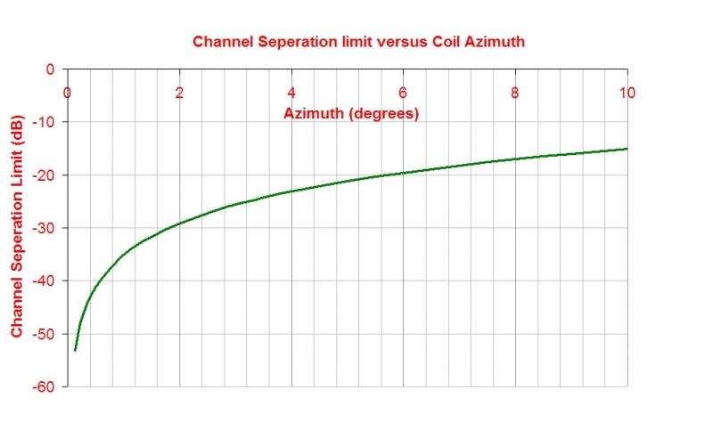
Crosstalk depends solely on coil azimuth, not on stylus azimuth.jan.didden said:The xtalk graph is interesting - equal xtalk L>R and R>L is at 1 degree angle of the cart, but lowest is at about 1/3 degree angle. Question is: how is this related to the actual angle of the stylus? 1 degree difference between vertical stylus and horizontal top of cart body seems not unreasonable but it does mean that leveling the cart body in the hope to set the stylus exactly vertical is not always good.
Optimal crosstalk is a very sensitive setting, have you already seen this (calculated) plot for crosstalk versus coil azimuth which illustrates this sensitive relationship: ?
http://www.diyaudio.com/forums/atta...608193-vinyl-coefficient-friction-azimuth.jpg
Stylus azimuth, on the other hand, affects performance in many and various ways by influencing stylus-groove friction. Coil or stylus, it's often a trade-off of different factors, especially for a fine line stylus which can be very sensitive to friction variation via azimuth.
Last edited:
I'd look at Laloum's stuff. There are also some documents from Shure that discuss the interplay of mechanical resonance and electrical properties, if I recall correctly. The takeaway, again iirc, is that some intentional HF electrical resonance peaking is used to lift the top end of the MM/MI response. If you just fiddle with the electrical trying to make it as conforming as possible to RIAA, you may be missing some top end energy intended by the cartridge designer.Possibly I underconsidering the effect of the mechanical resonance, but I would have thought that, if you got Rload wrong then there would be a very obvious change in the frequency response above 8KHz (in the Cordell case) and you would know by inspection which way to tune it.
But I have no idea what the mechanical resonance does to the response and if that is significant enough to be of concern. Does anyone bother with a parametric to deal with this?
- Status
- Not open for further replies.
- Home
- Member Areas
- The Lounge
- John Curl's Blowtorch preamplifier part II