High OLG frequency corner of AD825 is here only for the reason that it has quite low Aol at low frequencies (70 - 76dB, according to the datasheet). It has quite high noise. John Curl's reasoning is not engineering reasoning anymore, it is a marketing reasoning focused on support of his designs/products and amazement of the non-professional public.
I already gave that information plus referred to David's complete spec info on another forum. Here it is on line #57469.
This particular test shown, I found from david, was at 100 Ohms and 2.7v rms. Looking for double that level, if possible.
Showing pretty good IC amp performance at -110-120dB at moderate loads doesnt get here. I could do discrete that good, myself. You guys are my experts. My hero's. What can you do for him?
THx-RNMarsh
Thanks for your irony
")
The AD4898 kept that low distortion (-110dB to -120dB) up to 2Vrms/150 ohm. I do not know if 150 ohm is a "moderate" load for an opamp. It was just practical. My preamp has 100 ohm output series resistor, so I used 50 ohm terminator for measurements.
Regarding 2.7Vrms/100 ohm, the "best" measurement I have at similar level of any amplifier I have is at 3.536Vrms and 6.8 ohm load. Unfortunately, the measurement is affected by distortion of the method itself, which is almost same as the result measured. The result is for OPA627 with "some buffer"
Attachments
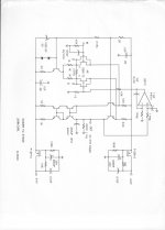
Here is my discrete version of this topology from about 20 years ago.
I thought we were talking about a line stage? This is a phono stage with the 75uS correction - better be low noise!
jan
Two listening test results in (one by pm). Which are interesting......
Up to now these to results show that differences and preferences may be discernable.
Any more takers ?
Mooly, I'd love to have a listen, but I have problems accessing dropbox. Can you upload files somewhere else? Thanks.
EDIT: FTP would be cool.
Last edited:
Mooly, I'd love to have a listen, but I have problems accessing dropbox. Can you upload files somewhere else? Thanks.
EDIT: FTP would be cool.
Try this for the shorter file. If its OK I can upload the other. These are on Onedrive.
http://1drv.ms/1DFFwNY
Does the frequency where the slope starts to fall (OLG) have any affect on the harmonic order of distortion harmonics?
Loop gain has it's merits, but I think the idea is a bit overhyped for certain applications and so many are inspired with false confidence when there's more to it. I think in many cases everything looks like a nail here.
Open-loop distortion is divided by loop gain resulting in output distortion. You cannot get the result of that equation without having BOTH of the input terms. Open-loop gain cannot be separated from open-loop distortion when you're trying to understand the distortion of a circuit.
For instance, the OLG corner frequency may be at 10KHz but the open-loop distortion may begin to rise at 100Hz. Or maybe at 15KHz it actually drops. In a distortion context, open-loop gain and open-loop distortion cannot be treated exclusively.
Of course understanding the distortion half of this equation is what requires you really get into the guts of the amplifier and understand how everything interacts.
Point is, wishful thinking is not substitute for getting in the guts. The guts stink, but you can do it. It's just a bit uncomfortable.
The guts stink
Same question remains, dead OLG zone or even (&low) distributed distortion ?
I'm not sure what you mean by distributed distortion, but now that I think about it, with a 12db/oct OLG slope, the feedback phase is nearly 180 degrees. The whole idea behind feedback is that you apply the error signal so that it goes against itself, but how can you do that when the feedback signal gets flipped backwards? There are many examples of amplifiers having low distortion in this feedback region so obviously it still works like feedback generally does.
I guess it takes a feedback wizard to answer this question. Maybe I'll figure it out eventually, might lead to some creative ideas...
EDIT: I figured it out. The errors are not reversed in phase, only the gain. So the errors are still in phase and are divided normally by the open-loop gain. That's my best explanation so far anyways. Well, maybe that still doesn't make sense. Still thinking (or maybe it does...).
Last edited:
Richard,
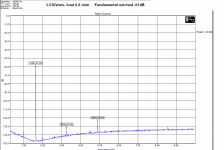
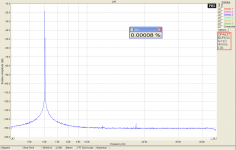
the best measured result obtained at a colleague of mine, who has better measuring equipment, is this one. Conditions are written in the red rectangle at the right side of the image.
BTW, David has already contacted me.
10K load is a problem what about driving low z loads?
THx-RNMarsh
maybe that still doesn't make sense.
Why so difficult, I was only referring to the open loop bandwidth part.
For closed loop gain, it makes diddly squat difference whether OLG runs out of breath below 20kHz, or drops 40 points between 20-20kHz as e.g. an AD797.
But for error ratio it does, which is a good thing (imo)
let me ask the same question -- what affect on harmonic structure of the distortion does the OLG freq response have? ...What affect does the OL BW have on the order of harmonics..... odds and even distribution.
THx-RNMarsh
If an audio signal falls in the falling slope region of the OLG, then in general the THD signal will have more high-harmonic content. If your OLG falls at 6db/oct, at best your harmonics will be as though they are passing through a 6db/oct HP filter. So the 2nd harmonic will be doubled, 3rd harmonic will be tripled, and so on... But if it's 12db/oct, your 2nd harmonic will be x4, 3rd harmonic x6, 4th harmonic x8, and so on...
Again, that's in the best case. Often what happens is that while the highest harmonics do get boosted, your low harmonics also get boosted because you're leaking distortion into the gain path.
And yet, the same thing can happen even without the aid of special OLG slopes. Any capacitance in the gain path can do this, cascodes can be worse if you use them with super slow transistors. Making generalizations here just inspires false confidence. There is a limit to what you can know unless you have actually studied the specific circuit in question.
Errors where there is less OLG get reduced less. So more HF harmonics in general. But it still depends on where the 2nd order compensation is put. IE you can add a resistor and a cap to an amp to make it a two-pole compensated amp but the resistor might be in a position where it's leaking distortion into the forward path rather than simply reducing gain at the right frequencies. This is why very often when you add more complex compensation, the decrease in distortion is not proportional to the increase in OLG.
Last edited:
- Status
- Not open for further replies.
- Home
- Member Areas
- The Lounge
- John Curl's Blowtorch preamplifier part II