Isn't it almost universal when we use lumped sums and approximations that we find these types of inaccuracies? Rounding errors are just as pernicious in many equations, I try not to round values off until a final result, with today's computers and other analysis systems it seems a lame thing to do. Perhaps when we were still using a slide rule it was the way to do things but why when you can go to so many digits to the right of 0 would you do it at all?
Here is a practical example of using skin depth to improve functionality: High Voltage Cable The hollow cables were supposed to work as well as a solid cable at 60 Hz and weigh less (cost less). I have a sample somewhere.
Nevertheless it s a very interesting design and shows what could be done, if the resources are there and parts are available. It is also interesting, at least for me, to observe the evolution of your designs, so, thanks for putting it up, it's very educational.Now, back again to the phono design. This design is the rough equivalent to a Bentley in the auto world. Big, powerful, effortless, remote controlled, and expensive. This is for the very wealthy or at least committed to the best that audio can be. It is impractical for the rest of us.
(I hope you won't get in trouble for doing it with people who write your checks).
Best,
Perhaps when we were still using a slide rule it was the way to do things but why when you can go to so many digits to the right of 0 would you do it at all?
Because most of those digits are meaningless. You may have a nice-looking result with 16 digits after the decimal place, but if your starting measurements were +/-0.1 then most of your result is garbage. Understanding the limits of your measurements and calculated results is important. It is understanding the difference between accuracy and precision.
Nezbleu,
I understand the difference from accuracy and precision but that wasn't the point I was attempting to make. I think the real point was what happens when you use approximations or lumped sums rather than precise numbers. I was just making the point that many times it isn't much harder to use accurate values rather than approximations and that lumped sums can also lead to errors in precision. I'm not saying to add extra or unrealistic decimal values but if you know a value is say 0.000563 why use 0.0006 as a rounded value?
I understand the difference from accuracy and precision but that wasn't the point I was attempting to make. I think the real point was what happens when you use approximations or lumped sums rather than precise numbers. I was just making the point that many times it isn't much harder to use accurate values rather than approximations and that lumped sums can also lead to errors in precision. I'm not saying to add extra or unrealistic decimal values but if you know a value is say 0.000563 why use 0.0006 as a rounded value?
That is a different issue. I'm not talking about a rough calculation using the right formula, but a possibly exact calculation using the wrong formula. The result can be a number which contains no significant digits, yet it looks fine.Kindhornman said:Isn't it almost universal when we use lumped sums and approximations that we find these types of inaccuracies? Rounding errors are just as pernicious in many equations
The example which cropped up here is characteristic impedance of a transmission line. The formula which everyone knows is sqrt(L/C), but this is only a valid approximation in the region where resistance is small when compared to inductive reactance. Otherwise this does not give an approximate answer but a completely wrong answer. jn knows this, but temporarily forgot to say. Many audio people don't know this, which is why you see people sometimes trying to sell "8 ohm" speaker cables.
Why is your cable impedance so high , I'm using pretty thick copper , much thicker than yours , possibly twice as thick, I will look at my notes on it and confirm .
Not following you, are you callingthe 4 conductor side by side the wide spacing..? how are you terminating at ends, side by side or do you xover...?

It is not the conductor resistance I am calling the impedance, it is the high frequency transmission line impedance, derived from the equation Z = sqr(L/C).
After I posted the measurement graph, I realized that the top data is that of a two conductor copper strip pair that had a 1.5 inch gap between the inner edges of the copper. The picture is of a valhalla clone, designed so that I could confirm their claim of propagation velocity by measuring the L and C of their construct. Their velocity was too high, .95 IIRC, so I wanted to duplicate it. They had inductance on their site at 900 nH per foot, which was off by a factor of 10 (a typo I believe), so that prop speed was not consistent. The correct inductance was actually 90 nH per foot, as my measurements did confirm, and it made me realize that the geometry causes a path reluctance which is higher than typical round conductors.
OMG...Ramo, Whinnery and van Duzer... I haven't heard that set of names in 40 years...hopefully, the nightmares won't return...I think the skin depth issue for a round wire is covered somewhere in Ramo, Whinnery and van Duzer - most textbooks omit it which is why so many people are not aware of it.
Back in '74 I was taught that the power companies use solid copper up to about 3 or 4 inches diameter. Beyond that, for 60 hz power, they went to hollow tubes with 2 inch wall diameters. They had the option of DI water cooling the tubes if they wished.Here is a practical example of using skin depth to improve functionality: High Voltage Cable The hollow cables were supposed to work as well as a solid cable at 60 Hz and weigh less (cost less). I have a sample somewhere.
Actually, I've been saying it all along. sqr(L/C) gives the hf Z, and at audio frequencies the actual impedance is typically a factor of 2 to 4 higher. I've stated that the equation gives a LOWER limit on the cable impedance, and an UPPER limit on the propagation velocity.That is a different issue. I'm not talking about a rough calculation using the right formula, but a possibly exact calculation using the wrong formula. The result can be a number which contains no significant digits, yet it looks fine.
The example which cropped up here is characteristic impedance of a transmission line. The formula which everyone knows is sqrt(L/C), but this is only a valid approximation in the region where resistance is small when compared to inductive reactance. Otherwise this does not give an approximate answer but a completely wrong answer. jn knows this, but temporarily forgot to say. Many audio people don't know this, which is why you see people sometimes trying to sell "8 ohm" speaker cables.
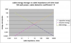
The selling of an "8" ohm cable for an 8 ohm load is actually quite reasonable from an engineering standpoint. Think about the total energy being stored within the cable at DC for example. The inductive storage is indeed 1/2 LI2, the capacitive storage is indeed 1/2 CV2, and it is a minima when the load impedance matches the line impedance.
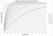
When the hf impedance matches the load, the settling time of the cable/amp/load system drops to the propagation transit delay, which is roughly 20 nSec for a 10 foot cable. (yes, the tail does slow down significantly as time goes on and inverted time drops into the audio band). But when the hf impedance is several orders of magnitude higher than both the source and the load, the settling time of the system increases 3 to 4 orders of magnitude, bring the settling time into the domain of human perceptions of ITD.
The only issue with very low Z cables, is that the load decouples at high frequencies, and if the amplifier's unity gain frequency is higher than where the load decouples, the phase margin is compromised. A zobel at the load can fix this.
jn
Last edited:
It is not the conductor resistance I am calling the impedance, it is the high frequency transmission line impedance, derived from the equation Z = sqr(L/C).
jn
I realized last night that I was only interested in the AC series R, just was interested to see if Mr Wayne's 1 Ohm speakers could be affected (only need 10's of mOhms to get 1/10ths of dB's). That 1934 reference as far as I can tell used concentric cylinders for their results so maybe I should look up Ramo. The AC resistance of wire must be tabulated somewhere?
I realized last night that I was only interested in the AC series R, just was interested to see if Mr Wayne's 1 Ohm speakers could be affected (only need 10's of mOhms to get 1/10ths of dB's). That 1934 reference as far as I can tell used concentric cylinders for their results so maybe I should look up Ramo. The AC resistance of wire must be tabulated somewhere?
Mr Wayne should do a very simple test.
Connect both speakers to one amp channel using identical wires.
Listen at the sweet spot to verify that all of the spectra of any music he chooses appears in the exact same point in space.
Then, replace one cable with a low impedance cable.
Repeat listening at the sweet spot.
If ANY of the spectral content has been time or level shifted such that the image is no longer spectrally confined to the exact same single location, then the cable parameters have caused a change which has risen to audibility within the confines of this specific test setup.
If all the spectral content still remains in the exact same location in space, then the cabling has caused no audible change.
Using one amp channel with two different cables is the most severe test. If it produces no discernable shift in any of the spectral content, the issue is dead.
If it does, then further study is warranted.
edit: sheesh, I only went down to 2 ohms in this..1 ohm settles even slower.
edit 2: This graph is the settling time for a transmission line using the hf equation. It is the MINIMUM time that the system will settle. If the actual audio frequency impedance and propagation delay were used, these delays would be 3 to 4 times LONGER. The 2 ohm line is about 4 uSec to 50% of final value, it would climb to over 10 uSec with actual t-line numbers, and 1 ohm settling to 50% would climb into the 20 uSec realm..
jn
Attachments
Last edited:
Your statement is correct if you have a given cable and wish to adjust the load impedance to minimise stored energy.jneutron said:Think about the total energy being stored within the cable at DC for example. The inductive storage is indeed 1/2 LI2, the capacitive storage is indeed 1/2 CV2, and it is a minima when the load impedance matches the line impedance.
That is not the situation with loudspeakers. There we have a given load impedance and can adjust the cable; the result then comes from minimising L and C.
This is analogous to the situation for maximum power transfer from a generator to a load. Given a generator output impedance we set the load equal to it. But given a load impedance we want the generator impedance to be as low as possible.
A problem and its inverse don't always have the same solution! Note that I am not commenting on the desirability or otherwise of minimising cable stored energy, just on how you would do it if you wanted to.
Your statement is correct if you have a given cable and wish to adjust the load impedance to minimise stored energy.
That is not the situation with loudspeakers. There we have a given load impedance and can adjust the cable; the result then comes from minimising L and C.
It is identical in all respects. Had I normalized the data, you would not be trying to pick them as different.
L and C tradeoff. LC = 1034 DC for constrained cables (actually, epsilon*mu for DC, but generally speaking, mu is 1.), and for standard zips, use EDC in lieu of DC, with EDC in the 4 to 10 range based on conductor spacing (due to field existing outside the conductor pair).
To minimize both, you have to go either stripline or coaxial, or do a paralleled cat5e style cable, giving EDC of about 3 to 4.
Remember, a speaker load varies. If the load varies from 1 ohm to say, 50 ohms across the audio band, then the settling time will be heavily frequency dependent. If the cable is a 300 ohm cable (typical zip at audio frequencies btw, it's hf Z without R or G is about 100), then this speaker/cable combo will settle in a long time at the 1 ohm frequency, and far faster at the 50 ohm frequency.
I would recommend making a cable's audio Z somewhere between minima and maxima load impedance.
What I am speaking of is both sides of the equation, and the relationship.A problem and its inverse don't always have the same solution! Note that I am not commenting on the desirability or otherwise of minimising cable stored energy, just on how you would do it if you wanted to.
Doing it is quite simple. A zip runs 100 ohms hf. Twist 4 zips with orthogonal pitches, then parallel them, giving 25 ohms, or 8 giving 12.5 ohms, or about 35 to 50 at audio frequencies.. Then, the only remaining Q would be conductor resistivity vs bundle size.
edit: your generator with impedance argument falls apart in the audio solid state power amp domain. Most amp Z outs are very low by design.
jn
Last edited:
Go through the maths of the stored energy minimisation problem, as I did before answering your post. I suspected you were wrong, but I didn't want to reply before I had checked it. You will find that given a particular cable L and C you get minimum stored energy when the load impedance R is sqrt(L/C) (as you said). Now fix R and allow L and C to vary; you will find that minimum stored energy comes from minimising L and C (as I said). Simple maths. Different problem, so different answer.
Interestingly, the 'end-on' configuration of wide flat conductors will probably deliver low L and C.
Interestingly, the 'end-on' configuration of wide flat conductors will probably deliver low L and C.
I should have known this problem is rather complex. I thought only the ancients were this facile in big maths.
http://www.g3ynh.info/zdocs/comps/Zint.pdf
http://www.g3ynh.info/zdocs/comps/Zint.pdf
Last edited:
That is accurate.Go through the maths of the stored energy minimisation problem, as I did before answering your post. I suspected you were wrong, but I didn't want to reply before I had checked it. You will find that given a particular cable L and C you get minimum stored energy when the load impedance R is sqrt(L/C) (as you said).
You've neglected the velocity of light. Tsk, tsk...Now fix R and allow L and C to vary; you will find that minimum stored energy comes from minimising L and C (as I said). Simple maths. Different problem, so different answer.
")
L and C tradeoff. You can only minimize both by constraining both the E and M field as in a coaxial cable or stripline.
LC = 1034 DC.
DC = LC/1034.
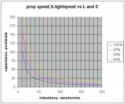
Vprop = 1/sqr(DC)
Make both L and C too small, Vprop exceeds lightspeed.
edit: I've attached a few graphs. First, the direct relationship between hf prop velocity, L, and C for 4 velocities.
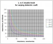
Second, the relationship between L, C, and DC for a coaxial cable.
Third, the energy storage relationship between cable Z and load Z. As DF96 apparently concurred, this relationship holds from DC to daylight.
jn
Attachments
Last edited:
Oops! Yes, you are right. It is a constrained optimisation problem.jneutron said:You've neglected the velocity of light. Tsk, tsk...
L and C tradeoff.
I am still not convinced that minimising energy storage is desirable, but that is a separate issue. I guess it is the lumped version of your settling time ideas, which we have already argued about in the past.
I should have known this problem is rather complex. I thought only the ancients were this facile in big maths.
http://www.g3ynh.info/zdocs/comps/Zint.pdf
Thanks. Now my eyes are bleeding..
jn
I am still not convinced that minimising energy storage is desirable, but that is a separate issue. I guess it is the lumped version of your settling time ideas, which we have already argued about in the past.
That's ok, my beliefs are independent of what you are convinced of.
Seriously though, this delay stuff has been measured by Cyril Bateman at audio frequencies using a modified RF bridge.
The settling time exists, it's as I've stated, it's been measured by others... It's the settling time across the entire audio band that's important, but only if one wishes to maintain the soundstage virtual imagery. Me, I've no audio system that is very capable of that. Nor, any desire to try to own one.
The only thing left is to test for audibility. that would determine desireablility..
jn
Last edited:
Seriously though, this delay stuff has been measured by Cyril Bateman at audio frequencies using a modified RF bridge.
Links, pictures? I am skeptical of the audibility also. The waveforms are clear why can't a direct measurement be done? Was your plot a voltage step at one end and the voltage at the other end?
again: proximity effect is more important than isolated round wire skin effect calculation to 0.1% in audio cables
and we can sim - not that I went far enough in quickfield http://www.quickfield.com/ to extract the Z
http://www.diyaudio.com/forums/everything-else/193100-speaker-cable-myths-facts-15.html#post2651247
sim is mirrored about left vertical edge with opposed currrent conductor to show the Proximity effect, current crowding to the inside edges of the conductors
Last edited:
- Status
- Not open for further replies.
- Home
- Member Areas
- The Lounge
- John Curl's Blowtorch preamplifier part II