Jan, have you ever tried those vinyl plug-ins? I have - in the hope that emulating some of the defects of vinyl might give it "that sound". I.E., is it the flaws of vinyl that we like?
I found the effects awful. Maybe I just wasn't good at using the software, but it never sounded better than a crude gimmick to me. Was wondering if anyone else had better luck.
Jan's list does not include things I think matter. Stylus shape and AM/PM from the inevitable inability to trace the groove is one. This is actually not that difficult of a mathematical exercise. Most of Jan's list are things that are minimized on on my favorite LP's.
Do any of the plug-ins simulate wet play?

Scott - speaking of the recording you did chez SY, I've heard it and liked it a lot. In fact it was a bit of a game changer for me. It seemed to combine the best of analog and digital sounds. It was super clean, low noise, low distortion - but also just as warm and pretty as you could want. At least without going for an effect. Not cold or digital sounding at all. Wavebourne's recordings are similar.
Which leads me to wonder how much of analog warmth is the addition of certain artifacts and how much is the lack of others that typically come with the A/D chain?
Which leads me to wonder how much of analog warmth is the addition of certain artifacts and how much is the lack of others that typically come with the A/D chain?
For LP to digital cleanup, I use the Steinberg "Clean" software to remove the click & pops in the captured .wav file. I find it works very well. You can set the thresholds while listening to the tracks, as soon as it starts to distort, back it off a bit then process the batch.Real simple.
It is obvious that 'my world' of phono reproduction is not the same as many people here.
My references are digital free. That is the only way that I know to make vinyl really exceptional, and not just the same old stuff that we get every day from TV, FM, and CD's.
As far as SY's questions:
1. Input capacitance is NON-LINEAR so it can be important, especially with MM cartridges. It also reduces the high frequency input impedance in some cases.
2. Input linearity is very important in my designs, because the input devices set the linearity for the entire first gain block.
3. I have designed for 0.4nV/rt Hz for the last 40 years, successfully.
First, with paralleled 2N4401-3 complements, later with 2SK146-J73 jfets.
The primary difference between the two approaches, for example, the Levinson JC-1 and the Vendetta Research SCP-1, was not input noise, per se, but DYNAMIC HEADROOM.
And operating 'open loop' the SCP-1 has 100 times lower distortion than the Levinson JC-1, although they have the same function to amplify the phono signal to a more easily handled voltage level.
My way of handling input noise, is to get a Noise Figure of 3dB with an added 10 ohm resistor at the source. This eliminates tedious measurements of noise over frequency, and gives a realistic indication of where we are at, noise-wise.
The original Levinson JC-1 was designed to amplify the original Ortofon phono cartridges that had only 50uV output at operating level. The vinyl record S/N is a completely separate set of tradeoffs. What I felt important is get an S/N from the phono cartridge- preamp system that is as close to the phono cartridge resistance alone as possible. A 3 dB NF with 10 ohms is NOT a perfect solution, if the phono cartridge has only 2 ohms of resistance like the Ortofon.
Thankfully, new MC cartridges were introduced with more output along with higher intrinsic resistance, so both the Levinson JC-1 and the later Vendetta SCP-1 got even better S/N with these newer phono cartridges, and achieved a lower NF as well.

1. Input capacitance is NON-LINEAR so it can be important, especially with MM cartridges. It also reduces the high frequency input impedance in some cases.
2. Input linearity is very important in my designs, because the input devices set the linearity for the entire first gain block.
3. I have designed for 0.4nV/rt Hz for the last 40 years, successfully.
First, with paralleled 2N4401-3 complements, later with 2SK146-J73 jfets.
The primary difference between the two approaches, for example, the Levinson JC-1 and the Vendetta Research SCP-1, was not input noise, per se, but DYNAMIC HEADROOM.
Thanks, John. I restricted my question #1 to MC- for MM, a FET or tube is clearly advantageous because of current noise. Restricting ourselves to MC, yes, the input capacitance is slightly nonlinear, but the input voltage for signal is (max) a few tenths of a millivolt. What's the input capacitance change over that signal swing?
For #2, I'd ask again how much the linearity difference matters for very small signal swings characteristic of first stage signal? In other words, what distortion would one expect with a low rbb bipolar versus an FET in that position with a couple of tenths of a millivolt?
For #3, I'd ask again, what are the s/n differences between a bipolar and FET in the first amplifier considering stage gain?
Thanks for the opportunity for real technical discussion.
Which leads me to wonder how much of analog warmth is the addition of certain artifacts and how much is the lack of others that typically come with the A/D chain?
For a long time I have though that there is a curious similarity to the artifacts of things like SET amps and vinyl, at least in a generic way (AM/PM). Note Ron Quan's tests of some popular tube amps for example.
For the Austin recordings we used mic's with 100% feedback to the capsule so the distortion was extremely low (for a mic) all the way to 8V p-p out which was not even approached in this type of music. Even SY's clapping simply activated the Fostex soft clipper a few times, the mic never clipped. BTW the 8V p-p represents 123dB SPL, for some uses I would set the mic up for less gain for instance at G = 1 this would be 143dB SPL and then mechanical capsule distortion might come into play.
That's my philosophy, nail the noise and undistorted dynamic range and you're 99% there.
Last edited:
That's my philosophy, nail the noise and undistorted dynamic range and you're 99% there.
Interestingly, that was the only manipulation I had to do when mastering those recordings- attenuate the applause (my fault!). In his latest release of songs, Southpaw included the recording of his cover of "I Wanna Dance with Somebody." It does sound startlingly different than the other recordings!
OK, so plugging in gms (bipolar gm being the highest), it looks like the FET noise will always be higher for a given current. BTW, it's been pointed out by many that the tube noise is somewhat worse than the equation you give- depending on whom you ask, it's between 2 and 10 times higher, in fact.
What about the amount of nonlinear capacitance and distortions at the signal swings characteristic of the first stage that you talked about before? Have you quantified that? How does the nonlinear input capacitance affect MCs?
What about the amount of nonlinear capacitance and distortions at the signal swings characteristic of the first stage that you talked about before? Have you quantified that? How does the nonlinear input capacitance affect MCs?
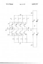
Now that the schematic for the Levinson JC-1 has been put up. Let's look at the good, bad, and uglies of this circuit:
1. This is one of the quietest approaches for getting a low noise phono stage.
While, 40 years ago, it was limited to 0.4nV/rt Hz, today it could be 0.2nV/rt Hz or even lower, with very low Rbb' parts and resistor value scaling.
2. Using a summing type input, allows the design to change its gain with different MC cartridges, lowering the gain significantly for a Denon, for example, compared to an Ortofon. This keeps most cartridges within a relatively linear region.
3. The max rated output is only about 0.1V rms. This is a serious limitation, IF you do not realize that the gain stage is designed to be in front of a normal phono stage, and 100mV, would give about 10V out at 1KHz in a typical phono preamp.
This design was very successful for several years, but I consider it obsolete today, because of its limited output capability.
Now how to we estimate the noise? Well, the Levinson JC-1 has 8 separate PARALLEL (from an input noise point of view) gain stages so the effective noise resistance is 1/8 of any individual gain stage.
Let's say that the transistors used have an averaged Rbb' of 40 ohms, and the current through each device is 1 ma.
We know from other engineering examples that the Gm for each device will be 40,000mho's which with .5/Gm= 13 ohms. Then we add Rbb' (40 ohms) and the ballast resister (10 ohms) and we get 63 ohms. Now, 63/8 gives about 8 ohms or about 0.4nV/rt Hz
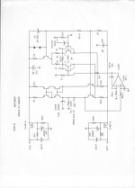
Now, let's look at a more convenient design, developed 20 years later, the can use either jfets or bipolars in the input stage:
This design is theoretically the square root of 8 times noisier than the original Levinson JC-1, but it does have much more dynamic range.
Newer bipolar and jfet parts make this design 'practical' when it was almost too noisy, back in 1973.
This design is theoretically the square root of 8 times noisier than the original Levinson JC-1, but it does have much more dynamic range.
Newer bipolar and jfet parts make this design 'practical' when it was almost too noisy, back in 1973.
Attachments
Last edited:
Of course the hollow state 1/f corner is usually much higher frequency than the JFET.OK, so plugging in gms (bipolar gm being the highest), it looks like the FET noise will always be higher for a given current. BTW, it's been pointed out by many that the tube noise is somewhat worse than the equation you give- depending on whom you ask, it's between 2 and 10 times higher, in fact.
What about the amount of nonlinear capacitance and distortions at the signal swings characteristic of the first stage that you talked about before? Have you quantified that? How does the nonlinear input capacitance affect MCs?
The same reason that JFETs don't benefit very quickly from additional current, as pointed out by Scott and others, the weak 1/4 power inverse dependence of noise as a function of drain current, also (as I pointed out in a totally ignored thread about ribbon mic preamps) works in the other direction IF input capacitance variations (nonlinear or otherwise) with signal are unimportant: you can parallel JFETs indefinitely and get continuously better noise for the same amount of overall current, until certain new mechanisms come into play at very low per-device currents.
Of course we will find it better to run at healthy currents, unless power is limited (like a phantom-powered device).
When we worry about capacitances, returning to no restrictions on power, we can use series feedback and a super-low-Z feedback divider to remove the effects of variable gate-source C. And we can bootstrap the drains to remove the voltage-dependent drain-gate C variations. Another author has worried about these capacitances and claimed that they were an insuperable limitation, based on the appearance of no direct feedback to the gate, but that's incorrect.
Jan's list does not include things I think matter. Stylus shape and AM/PM from the inevitable inability to trace the groove is one. This is actually not that difficult of a mathematical exercise. Most of Jan's list are things that are minimized on on my favorite LP's.
Do any of the plug-ins simulate wet play?
Of course it's not my list - I just copied it from the website of one of the manufacturers of those plug-ins.
OT/ Got another sunburn this afternoon on the Costa Blanca. You can see that the Spanish economy is hurting - some bikini's now are apparently sold without a top part
jan
- Status
- Not open for further replies.
- Home
- Member Areas
- The Lounge
- John Curl's Blowtorch preamplifier part II