Does mosfets models follow exactly gate capacitors behaviors ? (real question)
My experience is limited to power mosfets of the IR and IXYS type, gen 3, die size 3 and up. There is a built in transmission line effect because the gate polysilicon is sandwiched by SiO2 between the silicon below and the source metalization cover above. If you turn it on very fast into a really low inductance load, you can destroy the device near the gate wirebond (because a small portion of the device has turned on). If you turn it off very fast, you will destroy the device on the other side of the source bond (because it is the last part of the device to turn off).
It's easy to perform failure analysis of this with a TO-3 can. Not so easy with an encapsulated device. (Note, this understanding helped in determining a snubber topology for a hf switcher.)
You are always welcome.Thank you again jn.
George
You do not understand the problem as I meant..probably poor explaining on my part... That is of course not an issue which will stand between us. If you wish to discuss it further, PM me. Or, we can do here for the benefit of others.Unfortunately, that is not correct.
Frank
I do not understand how eddy current damping will be affected by the conductivity of the conductor. VC's by nature do not have large cross section wires, so eddy losses should be very low into the hundreds of Khz.Because that would make the voice coil run much hotter than using copper. Also probably poorer eddy current damping but that might not be an issue in some cases.
I am confused. Copper should have a higher conductivity.I was referring to efficiency losses with power, due to thermal coefficient. (What do you think ?)
But i have the answer:
Constantan conductivity = 49 E-8
Coper= 1,7 E-8
edit: oops, missed the minus signs...my bad..

cheers,
jn
Last edited:
I do not understand how eddy current damping will be affected by the conductivity of the conductor. VC's by nature do not have large cross section wires, so eddy losses should be very low into the hundreds of Khz.
I wasn't thinking quite straight when I wrote this. In fact I intermingled two issues - plain damping, provided by the amp which is a function of the voice coil resistance and eddy current damping which is indeed a small effect. But so far this latter the only hypothesis I have for why the acoustics guys always said that lower resistance voice coils on bass units sounded 'tighter' (and they definitely preferred them) than high.
I wasn't thinking quite straight when I wrote this. In fact I intermingled two issues - plain damping, provided by the amp which is a function of the voice coil resistance and eddy current damping which is indeed a small effect. But so far this latter the only hypothesis I have for why the acoustics guys always said that lower resistance voice coils on bass units sounded 'tighter' (and they definitely preferred them) than high.
It sounds reasonable that low resistance vc's would be tighter. I believe the essence of "damping factor" is one of control of the conversion device by the amplifier. When I model an inductor using Ls/Rs, the Ls is the only part of the model which represents the conversion from current to magnetic field. (note that inductance is by definition the relationship between the current in the system and the total magnetic energy stored in the system as a result of that current. E = 1/2 L I^2.
I believe using Rs as part of the numerator in damping factor calculations is not accurate. It is a parasitic which dissipates energy, not part of the conversion process.
jn
Last edited:
Yes on reflection perhaps its the consequent lower inductance of lower resistance vcs which conveys their sonic advantage?
Damping factor (as traditionally defined, in relation to a nominal 8R) for an amplifier's output impedance I see as rather a misleading number in that much larger magnitudes convey smaller and smaller increases in damping. The difference between DF=50 and DF=500 isn't worth very much at all in practice.
Damping factor (as traditionally defined, in relation to a nominal 8R) for an amplifier's output impedance I see as rather a misleading number in that much larger magnitudes convey smaller and smaller increases in damping. The difference between DF=50 and DF=500 isn't worth very much at all in practice.
Why do you think so? I even downloaded the PDF and read it.
In your first response you assumed current PFB only.
In your second response you commend on a filter at the input which causes some boost below Fs. This is not what goes on in that patent.
If you have the desire to go past your initial assumptions I am sure you will notice the methodology.
Whatever you do is OK for me. Just please yourself. Remember, this is a hobby
That patent did not address the variations of coil electrical Z.
It is due to the nature of the proposed compensation (not a boost filter), that this omission causes - as an unintended consequence - the formation of a 18db/oct LP filter around 100Hz. (not bad in the case of a subwoofer
). For a good explanation of the above, read Bass amplifier with high frequency responseOne invention that attempts to address a lot more issues (of the driver, driver coil, speaker box and cable) than Stahl, is here:
Impedance compensation circuit in a speaker driving system
By design, it is not restricted to a particular freq. range or for an enclosure type.
As a conception, I find it robust.
It turns to be complicated in the implementation.
Apart from this, results I guess will depend on the “fit” of the equivalent impedance model (item 4) and on the time constant of the integrator (item 52).
Of course, as every “load current sensing” method I have seen, it makes use of current PFB to a degree.
George
Yes, unless complicated eq around vent and cone resonance, bad time for vented boxes. That what we experimented too.You then must eq the system to get the desired response....The loop delay on any servo really limits what you can do.
Same for bandwidth. Reserved for subs. Then appears an other problem, homogeneity with the upper driver... short waterfalls in servoed sub, long in basses.
Did-you mean a coil on the LS back plate is able to sense changes in the magnetic field due to moving coil's movements? If so: brilliant idea !!!!We actually had an acceleration servo derived from back emf as well.
If it is not a problem for you to be more talkative about-it, you have teased my curiosity.It used a variation on a metal detector to sense the position of the diaphragm
For having experienced the work involved in servos for Loud Speakers, may-i congratulate-you for your courage and perseverance (and innovative ideas) ? As you said, it is pretty complex...
The passive filters of my enclosure (misses the compensation for the crossover itself):
Attachments
There is a built in transmission line effect because the gate polysilicon is sandwiched by SiO2 between the silicon below and the source metalization cover above. If you turn it on very fast into a really low inductance load, you can destroy the device near the gate wirebond (because a small portion of the device has turned on). If you turn it off very fast, you will destroy the device on the other side of the source bond (because it is the last part of the device to turn off).
jn
I read it as a tribune to Ivor Catt.
George
Was-i so disagreeable with you ?I must send my lawyers to see you
Recorded.I tried optical methods and double coils too but the ACE stuff works so well that I abandoned the other stuf
Last edited:
John, what would you think about the added capacitors (parallel to dividers), pl see image.
Hi Pavel,
How did you determine the values of those capacitors (which are non-standard values)?
Why do you need to do this 0R1 resistor trick if you have Audyssey? Does the resistor trick provide stuff that Audyssey can't do?
I thought you understand the difference between damping of ringing and equalizing the rest of response that can't be tamed mechanically?
If you equalize the frequency response, no matter how flat is it's 2-d representation (level VS frequency), look at waterfall (time added) and you will see that sharp resonances still produce audible colorations because sounds on some frequencies decay longer than on others. Equalized sh*t sounds like equalized sh*t.
Good point Nelson Pass. 100 ohm or so resistors would need to be added, but it still WOULD be quieter than my original design.
Hi John,
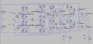
Will it work also with JFETs as the folded cascade, like in the attached schematics?
Attachments
If you equalize the frequency response, no matter how flat is it's 2-d representation (level VS frequency), look at waterfall (time added) and you will see that sharp resonances still produce audible colorations because sounds on some frequencies decay longer than on others. Equalized sh*t sounds like equalized sh*t.
I had indirectly asked SY which resonances are equalizable. He responded there:
No, that's not minimum phase and it's also not single-valued.
I took the risk to interpret his answer like this:
I don’t know if I guessed well.
George
I tried optical methods and double coils too but the ACE stuff works so well that I abandoned the other stuff. Also tried current drive but again ACE is superior. See my original post on the subject. I'm sorry Wave didn't see any distortion reduction in his experiments.
Yes, small driver fluttering like a fly in small box would always generate more distortions than bigger driver in appropriate enclosure. Don't be silly, even when joking.
I have no idea, it's a closed box for dummies, in 5+1 receiver. Calibrated microphone goes with it. It asks to position microphone in 6 different places, does fast sweeps through all channels one by one, calculates levels, delays, EQ. From what it does as the result I conclude that it equalizes mic position - independent things storing results in non-volatile memory.Wavebourn -- which Aud auto EQ model are you using. I got hold of their 6 dsp channel PRO model. It works very well for EQ'ing headphones as well... just need a probe mic. -RNMarsh
Hi Pavel,
How did you determine the values of those capacitors (which are non-standard values)?
Same ratio as resistor divider. You know, 1/jwC for cap impedance. RC constant to cover low frequencies.
Cheers,
Monacor Carpower Raptor MK1 Funktionstest für Aspirin - YouTubesmall driver fluttering like a fly
Diameter 12"
Double spider on each side of the moving coil
Impedance (Z) 4Ohms
Resonant frequency (fs) 43Hz
Power rating (P) 1,000WRMS
SPL (1W/1m) 87dB
Linear excursion (XMAX) ±13.5mm
Last edited:
I don’t know if I guessed well.
Very well, but some quibbles: minimum phase can apply to nonlinear systems as well. The only requirement is that the phase be the derivative of the amplitude response wrt to frequency. And single valued functions indeed contain no loops, but if (for example) you have a 2d function unwinding in a 3d space, you can inadvertently have multiple values which are not loops in the 2d representation. Rooms have 3 dimensions (assuming the room size is time invariant!), the signal applied to them has one dimension plus time. So, no minimum phase (there's delays from reflections) and multiply valued (amplitude varies over space as well as time).
Monacor Carpower Raptor MK1 Funktionstest für Aspirin - YouTube
Diameter 12"
Impedance (Z) 4Ohms
Resonant frequency (fs) 43Hz
Power rating (P) 1,000WRMS
SPL (1W/1m) 87dB
Linear excursion (XMAX) ±13.5mm
Everything is relative.
Ya know...it kinda does, doesn't it??I read it as a tribune to Ivor Catt.
George
Buuuut...I have experimental evidence...he does not..
jn
- Status
- Not open for further replies.
- Home
- Member Areas
- The Lounge
- John Curl's Blowtorch preamplifier part II