LoL!
If we can't have a sense of humor around this stuff, why bother.
see what I mean?
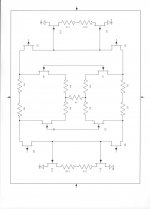
Rotate your "normal" schematic by 90 degrees and it gets scary. Who are your ancestors, John?
I am serious, by the way.
Last edited:

The REAL question is: WHY do I design this way?
Because that circuit will work, sound good, measure well and still work in 15 years. Plus if the parts are Toshibas it will go up in value.
Few days ago John mentioned importance of resistors used at NFB chain.
I did impedance measurements of some different type resistors, impedance behaviour above 100kHz is very specific for every individual resistor, and even below 100kHz some fluctuations of impedance modulus is observed (I'll post it late on). Another side of the story, what materials resistors are made of, and how "pure" manufacturing technology is.
I did impedance measurements of some different type resistors, impedance behaviour above 100kHz is very specific for every individual resistor, and even below 100kHz some fluctuations of impedance modulus is observed (I'll post it late on). Another side of the story, what materials resistors are made of, and how "pure" manufacturing technology is.
Attachments
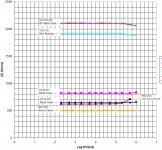
Here is the relative variation of the impedance modulus of various resistors with frequency. The vertical axis is |Z(f)| / |Z(200Hz)|, total span of the axis is +-2%.
Even at medium frequencies there are some ripples of impedance (possibly some electrostrictive deformation).
These results are taken at the same 1V RMS test sine signal. Impedance will also vary by the test signal amplitude variation. I am afraid to imagine what goes on with a given resistor when unstable schematics usually oscillate (10...100MHz).
Attachments
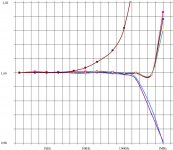
Here is the relative variation of the impedance modulus of various resistors with frequency. The vertical axis is |Z(f)| / |Z(200Hz)|, total span of the axis is +-2%.
Even at medium frequencies there are some ripples of impedance (possibly some electrostrictive deformation).
These results are taken at the same 1V RMS test sine signal. Impedance will also vary by the test signal amplitude variation. I am afraid to imagine what goes on with a given resistor when unstable schematics usually oscillate (10...100MHz).
Interesting - but fairly meaningless without details of the test set-up and equipment used.
Interesting - but fairly meaningless without details of the test set-up and equipment used.
I use mass produced immitance meter
IMMITANCE (RLC) METERS E7-20
•Immitance (RLC) Meter Å7-20
•25 Hz - 1 MHz, ±0.1%
•Wide frequency range 25 Hz–1 MHz
•Capacitance 10**(-15) to 1 F
•Inductance 10**(-11) to 10**4 H
•Resistance 10**(-5) to 10**9 Ohm
•Conductance (10**(-11) – 10) S
•Complex impedance module (10**(-5) – 10**9) Ohm
•Reactance (10**(-5) – 10**9) Ohm
This is a manufacturer's site
????? | IMMITANCE (RLC) METERS E7-20
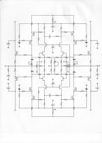
I just realized there's no need to upset the resistor network; here's another way to set the bias....IMHO, the easiest would be to use split feedback (assuming there is feedback). The resistor network between the JFET drains would need to be unbalanced to allow for the voltage offset between the gates of Q2 and Q4....
(Idea swiped from the Musical Fidelity A1, which also uses split feedback to set bias.)
Attachments
I just realized there's no need to upset the resistor network; here's another way to set the bias....
(Idea swiped from the Musical Fidelity A1, which also uses split feedback to set bias.)
What's the benefit of having bipolars at the output, over FETs?
I just realized there's no need to upset the resistor network; here's another way to set the bias....
(Idea swiped from the Musical Fidelity A1, which also uses split feedback to set bias.)
Still would benefit from cascode in output. These circuits get so linear that the Vas non-linear Ccb can add even up to 20dB to the thirds at 10kHz
BTW the avatar is "woman ball player", the Mayan version of "ball" had unfortunate consequences for the loser.
Last edited:
I just realized there's no need to upset the resistor network; here's another way to set the bias....
(Idea swiped from the Musical Fidelity A1, which also uses split feedback to set bias.)
Musical Fidelity A1 does not use current mirror loads, hence they don't have the same bias problem: http://www.tcaas.btinternet.co.uk/mf-a1.gif
Your bias solution doesn't seem to be good enough. In this configuration, assuming all bipolars and jfets identical and perfectly matched, Q7 and Q10 are saturated (Vcb=0).
Adding degeneration to the Q6 and Q7 emitters may help here. Though I am not sure if such a setup will conserve much of the maximum/ideal differential loop gain.
No doubt. The simple circuits were to show the idea, while (hopefully) avoiding "can't see the wood for the trees" syndrome.Still would benefit from cascode in output....
Dunno about that. I remember Olivier trying to follow Edmond's advise in this thread. After nearly a year, he still hadn't got it to work. My opinion at the time:...I thing we have to look to Edmond Stuart for inspiration.
FWIW, I think you really got suckered with that design, purely from a complexity point of view. Whenever I see a design with about 100 more transistors than strictly needed, my knee-jerk reaction is:"Well, I'm certainly not going to solder all of that". Sorry to say but I'm too lazy to even try figure out how it's supposed to work. Perhaps you haven't been getting much help because other forum members feel the same way?
Unfortunately Edmond seems to have abandoned diyAudio, so you're kinda stuck with it.
Edit: Huh? Where did Bonsai's post go?

P.S. Yes, I know Edmond came back later.
Last edited:
No, but it does have _a_ bias problem, and uses split feedback to fix it.Musical Fidelity A1 does not use current mirror loads, hence they don't have the same bias problem: http://www.tcaas.btinternet.co.uk/mf-a1.gif
They'll work with Vcb=0, but it would be better to put something (diodes/LEDs/other) between the emitters of Q6 and Q9 and the rails to provide some extra voltage drop. Especially if the mirror is degenerated, as it should be.Your bias solution doesn't seem to be good enough. In this configuration, assuming all bipolars and jfets identical and perfectly matched, Q7 and Q10 are saturated (Vcb=0).
Sorry, I don't follow. Where is gain being lost?Though I am not sure if such a setup will conserve much of the maximum/ideal differential loop gain.
- Status
- Not open for further replies.
- Home
- Member Areas
- The Lounge
- John Curl's Blowtorch preamplifier part II