I saw them already somewhere, with PCB ring with a chamomile of SMD capacitors soldered around.There seems to be scope here for a genuine audio gizmo: RCA socket with external ground tag, small cap, solder tag, bolt, nut, shakeproof washer. Sell in red and white pairs for $99, or $499 for the deluxe set of 5 pairs and a 12V minidrill for making the holes for the bolts. I can't write the sort of blurb these would need to sell, but I'm sure we could frighten people with thoughts about 'RF soup', 'radiation energy' etc.
Ah, but were they cryo'd??I saw them already somewhere, with PCB ring with a chamomile of SMD capacitors soldered around.
jn
Ed, the values and types of caps that I specified, were given to me 28 years ago by Scott Wurcer, along with a large file of actual measurements. I was making a 30MHz, 50W power amp at the time, and I needed the info. The values and types were put up to remind Scott Wurcer what he recommended I use on that project for medical electronics back then. These types and values have NOTHING to do with audio specifically, in fact I don't use this combination in ANY audio design that I have ever made. Since we seem to be intermixing military-industrial grade standards and solutions and attempting to apply them to high end audio solutions, I put it out there, because that combination, at the time, worked great for my RF project at the time.
Last edited:
As has been mentioned starved bipolar input stages are more susceptable to EMI (RFI).
Probably it is one of reasons why my mic pre with missile warhead triode 6S17K-V input sounds so nice compared to best solid state only designs.
Probably it is one of reasons why my mic pre with missile warhead triode 6S17K-V input sounds so nice compared to best solid state only designs.
Tubes are the most EMI resistant as a rule of thumb. Then come FET's and last are bipolar junction transistors.
So do you have the rest of the warhead?
So do you have the rest of the warhead?
Ar you sure such jokes are innocent?

Hi,
Ahh, so what if there a is a further RF barrier...?
Then the hole in the outside does not cause so much harm... Right?
Ciao T
Indeed. A further barrier between the rear panel and the interior of the device is necessary to avoid RFI entering the device. This further barrier may be small shields covering completely each and every socket, with feed-through capacitors in the shield connecting the sockets wires to the device, or it may be a second panel, between the rear panel and the device, with feed-through capacitors in the second panel connecting the sockets wires to the device. All this in addition to some other measures mentioned here, like a small capacitor with short leads from the (-) terminal of each socket to the chassis and RF choke in series with the (+) terminal.
Ar you sure such jokes are innocent?
Have you seen Jan's speakers?
Have you seen Jan's speakers?
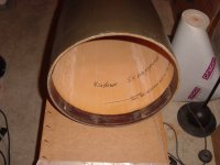
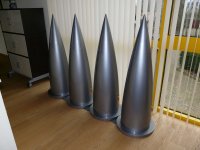
No. But I was thinking yesterday about conical shape for speakers. I did not figure out yet how I am going to mold concrete of such shape. The tip will be cut and turned upside-down to act as reflector for tweeter facing up, the bottom should have one more cone to reflect bass and mid frequencies around, with driver facing down. I want to compare sound of omni speakers with line arrays that I use currently.
Indeed. A further barrier between the rear panel and the interior of the device is necessary to avoid RFI entering the device. This further barrier may be small shields covering completely each and every socket, with feed-through capacitors in the shield connecting the sockets wires to the device, or it may be a second panel, between the rear panel and the device, with feed-through capacitors in the second panel connecting the sockets wires to the device. All this in addition to some other measures mentioned here, like a small capacitor with short leads from the (-) terminal of each socket to the chassis and RF choke in series with the (+) terminal.
Real audiophile Joshua must think big: how to surround the listening room by Faraday cage.
imo, JD should be living in a decommissioned nuke base.
Missile Base Properties for Sale
(ok, could be my wet dream instead)
Missile Base Properties for Sale
(ok, could be my wet dream instead)
imo, JD should be living in a decommissioned nuke base.
Missile Base Properties for Sale
(ok, could be my wet dream instead)
Wow, I like this one! I wold buy my share of DIY Audio community project based on this property. We can make plenty of acoustic laboratories underground for different kinds of measurements and offer them for rent to companies who have money.
Atlas F missile base, Adirondack Mtns, NY
Real audiophile Joshua must think big: how to surround the listening room by Faraday cage.
This isn't necessary. All we need to take care of is properly shielding each and every electronic device in our sound system against all EMI/RFI.
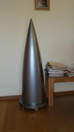
Final paint is BMW Arctic Grey.
Must be the world's first > 100k$ subwoofer
jan
A fake wood floor!
imo, JD should be living in a decommissioned nuke base.
Missile Base Properties for Sale
(ok, could be my wet dream instead)
I like the Titan silo myself. I was at a base that was converted to appartments, nothing like 8 urinals in your bathroom (great for parties).
urinals
I've got a SS head, still have to install it some time.
(shell-proof navy frigate, half-life renovation freebie, sentimental stuff)
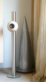
Of course, a Rocket sub needs a mid/high Bullet
"Big Brother is Watching Yoiu!"
- Status
- Not open for further replies.
- Home
- Member Areas
- The Lounge
- John Curl's Blowtorch preamplifier part II