Hi, I just bought a Ampro LCD-150 projector off ebay for really cheap. The only problem is it's bulb is out. I was thinking I could manage to set up a metal halide bulb instead. The problem i have is that it won't dispaly anything probably if there's a burnt out lamp, since the "Lamp" lcd is lit up. I was wondering if anyone had an idea to fool the thing into thinking the lamp works, so I can use it. I thought that maybe I could just close the circuit, and reduce the current to that used by the buld. Anyone wanna give me some advice here?
Hi,
I have been reading this forum for a while now, but never had the time to build anything. Although I bought the Fujinon lens and a small lcd etc to try and build a basic projector, it never happened.
Anyway, I have bought a Projector with no bulb either.
It took a while to fool it but it’s done now.
before we start..
DO NOT PUT YOUR DVM ACROSS THE IGNITOR OUTPUT.


altough it created a nice blue arc between the meter probes...lol
You need to look for a few things:
Safety Switches:
it won’t power up if any of the covers is open.
Fans:
they might have rev control, if the projector knows they are not working it might not power up to prevent overheating or fire.
Temp sensors:
Self-explanatory.
Lamp:
Mine (Mitsubishi S120) had the lamp led flashing red.( over 1900hours gone)
After looking on the manual all I had to do was press 2 keys to reset it.
And of course, the current sensing.:
This is the tricky bit!
First I fitted a small 150W halogen bulb in the lamp compartment with the hope it would only have optical sensors…L nope!!!
So I had then to take every screw and part of the projector to open the power supply.
It’s common to use Opto Isolators or Opto couplers for current sensing on power supplies.
http://uk.farnell.com/jsp/catalog/v...3Z5EACYPCQ3QFIAEWSFE4AVAAS0IV3?prodId=3565683
So look for these components. There will be at least 4 of them but the ones you want will be on the low voltage DC part of the PSU close to the igniters.
You should have one going active when U press “power” and the other should reply to the board once the lamp fires.
Look for 3 wires going to the psu from the main board, maybe.
All I had to do was to pull one line low and that was it…J.
The ballast, the igniter, and low DC part of the PSU ( made of 2 PCBs) aren’t even in the projector anymore.
I am sorry if it sounds complicated but English is not my native language.
I now have it working with a 15v 150W halogen bulb image is only visible with the room lights off but its ok, maybe a bit on the green side.
Hope this helps….
Any one knows how to build a 24v @ 10-15A PSU??
Or where to buy a cheap one?
Or maybe an easy and cheap way to power a 250w halogen bulb?
I have been reading this forum for a while now, but never had the time to build anything. Although I bought the Fujinon lens and a small lcd etc to try and build a basic projector, it never happened.
Anyway, I have bought a Projector with no bulb either.
It took a while to fool it but it’s done now.
before we start..
DO NOT PUT YOUR DVM ACROSS THE IGNITOR OUTPUT.
altough it created a nice blue arc between the meter probes...lol
You need to look for a few things:
Safety Switches:
it won’t power up if any of the covers is open.
Fans:
they might have rev control, if the projector knows they are not working it might not power up to prevent overheating or fire.
Temp sensors:
Self-explanatory.
Lamp:
Mine (Mitsubishi S120) had the lamp led flashing red.( over 1900hours gone)
After looking on the manual all I had to do was press 2 keys to reset it.
And of course, the current sensing.:
This is the tricky bit!
First I fitted a small 150W halogen bulb in the lamp compartment with the hope it would only have optical sensors…L nope!!!
So I had then to take every screw and part of the projector to open the power supply.
It’s common to use Opto Isolators or Opto couplers for current sensing on power supplies.
http://uk.farnell.com/jsp/catalog/v...3Z5EACYPCQ3QFIAEWSFE4AVAAS0IV3?prodId=3565683
So look for these components. There will be at least 4 of them but the ones you want will be on the low voltage DC part of the PSU close to the igniters.
You should have one going active when U press “power” and the other should reply to the board once the lamp fires.
Look for 3 wires going to the psu from the main board, maybe.
All I had to do was to pull one line low and that was it…J.
The ballast, the igniter, and low DC part of the PSU ( made of 2 PCBs) aren’t even in the projector anymore.
I am sorry if it sounds complicated but English is not my native language.
I now have it working with a 15v 150W halogen bulb image is only visible with the room lights off but its ok, maybe a bit on the green side.
Hope this helps….
Any one knows how to build a 24v @ 10-15A PSU??
Or where to buy a cheap one?
Or maybe an easy and cheap way to power a 250w halogen bulb?
I know it ‘s obvious but I better say it any way.
DO NOT connect an Halogen bulb to your projectors PSU. The Halogen bulb must powered from an exteranal power supply.
DO NOT work on the PSU with it connected to mains.
DO NOT disable any of the safety features (switches, sensors etc) built in your projector.
DO NOT TOUCH any of the mains part of the PSU even after powered off. Capacitors can still give you a violent discharge.
DO NOT try to measure the striking voltage…lol
Tuga: you said "All I had to do was to pull one line low and that was it"
I'm not sure what you mean here. Do you mean that all that you had to do was disconnect one cable? If I post a few pictures of my circuits, can you give me some advice? I think I've narrowed the Opto things to only a few possible ones, and you might be able to tell me which one I need to concentrate on.
I'm not sure what you mean here. Do you mean that all that you had to do was disconnect one cable? If I post a few pictures of my circuits, can you give me some advice? I think I've narrowed the Opto things to only a few possible ones, and you might be able to tell me which one I need to concentrate on.
Hi,
I mean there was a line that was high (+5v) until the Opto pulls it low (0V).
I have removed part of the circuit that had the optos so I connected that line to 0V permanently.
You said u narrowed it down. Take the numbers on those components and make a search on Google. If it mentions opto isolators or opto decouplers you know they are the ones.
You will need basic knowledge of electronics to figure out the circuit around them, so you know to which pin should you attach what voltage.
You will need a multimeter (DVM) as well.
Take all the safety measures.
About the “just throw a 250 watt MH in, and forget all the bypassing stuff” I have no idea.
That was going to be my next step if I couldn’t find a way to bypass it.
Now that I have a working projector I don’t feel like blowing it to bits.
I you decide to try this option remember that you are dealing with over 5000Volt pulse to ignite the lamp. You might want to try it with the lamp outside your projector….and take cover….lol.
But it might just work.
Keep me posted.
Good to hear that more people than I are trying this, also nice to hear that they use opto-couplings, that makes this thing more easy, I wondered how they know when the lamp has warmed up, but now I know that they can use opto-couplings. In my case I have a 20pin connection from the PSU so the problem is which pin do I have to pull down to 0V. The biggest problem I have is that I can´t get into the PSU without to take everything out of the projector.
As I have sad before I think this is the new DIY-video thing most people want to do in the future. Pro-projectors have all the advanced optics and electronics and better lcd:s already built in that diy-projectors can´t compete with. A pro-projector without the UHP-lamp is only worth the half of it´s price and that makes it more cheap than any other diy-projector. And the best thing with pro-projectors is that you can sell it, if you don´t want it. DIY-projectors is quite hard to sell ?
As I have sad before I think this is the new DIY-video thing most people want to do in the future. Pro-projectors have all the advanced optics and electronics and better lcd:s already built in that diy-projectors can´t compete with. A pro-projector without the UHP-lamp is only worth the half of it´s price and that makes it more cheap than any other diy-projector. And the best thing with pro-projectors is that you can sell it, if you don´t want it. DIY-projectors is quite hard to sell ?
Attachments
Hi,
I had a lot of big connectors from my main board to the PSU.
But these wires were going to what was easily identifiable as the low DC regulation part of my PSU (not live).
The connector that did it for me was actually on its own, 3 little wires…lol.
If it helps look for a chip with the numbers ***494** (ex:TL494, M5T494P or equivalent)
This is a PWM chip that controls the output of the PSU. Basically I THINK this chip controls the voltage after the ignition pulse.
Somewhere around this chip you maybe able to find the 2 Optocouplers u are looking for.
I don’t think it knows if the lamp is warm or not, it only knows if the arc has been formed.
My optos were made by Sharp, PC123 chips.
As I said, the igniter and optos are no longer inside my projector so I’ll take a picture when possible.
At the moment I am looking at trying a 240v 300w linear Halogen lamp (78mm) on mine, since I can’t find an easy ( and small ) way of powering a 24v 250W halogen one.
The lamp compartment should be just big enough since it has an 80mm fan at the end.
Has anyone actually tried to use a normal compact metal halide lamp on a Pro projector with the projector’s ballast and igniter??
If any one has any ideas …...
Hi,
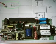
Here it is as promised, a pic of the half of my projector’s PSU that is no longer used.
Inside the red circle are the 2 OptoIsolators and 1 end of the cable that connects to the main board,
Inside the yellow one is the 494 PWM chip that is supposed to control the output.
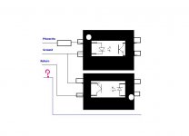
Inside the green circle is the other end of the cable and the drawing of the 3 lines ; “PowerOn”, Ground and the so important +5V that has to be pulled low.
The 2 squares on the schematics represent the “insides” of standard OPTO’s.
Hope this helps.
Here it is as promised, a pic of the half of my projector’s PSU that is no longer used.
Inside the red circle are the 2 OptoIsolators and 1 end of the cable that connects to the main board,
Inside the yellow one is the 494 PWM chip that is supposed to control the output.
Inside the green circle is the other end of the cable and the drawing of the 3 lines ; “PowerOn”, Ground and the so important +5V that has to be pulled low.
The 2 squares on the schematics represent the “insides” of standard OPTO’s.
Hope this helps.
Attachments
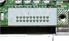
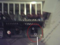
OK, here's a pic of the PCB (sorry for the crappy quality, my camera has no macro mode, so I had to use the old magnifying glass trick). I circled the 2 chips and cable connector which I belive are responsible. I drew in a white line where the white wire connects, as the other 3 are blue. I think that the white may be power or ground. I also circled in white where there's a white dot around the pin on the circuit board, maybe this will help. Now what's your advice from here? If you need a better pic, or one of more of the board, let me know.

Ok, that surely looks like it.
The fact that they are facing opposite ways (just like mine) PROBABLY means 1 is for the “PowerOn” signal and the other for the “I’m PoweredOn” return signal.
You gonna need to grab a meter and do a few things but
First:
 Do not power the Projector with the PSU opened. Lethal voltages inside.
Second:
Read the safety warnings on my previous post.
Third:
I take no responsibility of any damages done to your projector or to yourself.
Now we can continue, lol")
Draw 2 optos on a paper and try to complete the circuit around them.
Have a look at my drawing and try to compare.
1- Find out which wire is connected where exactly (the 4 of them).
2- Find out which wire is ground. This will be connected to both Optos on the same side as the connector. To do it, reconnect the wires to the main board and check for continuity between mainboard ground and the pins on the optos.
Don’t use the PSU ground since they should be different grounds. This is the main objective when using OptoISOLATORS.
Or if you have a meter that can test Diodes, with the Projet switched off, put the RED probe on the pin marked with the white dot and the BLACK probe on the other pin on the same side of the component. If it reads approx. 1V the Black is Ground.
If it reads 2.999, The RED is ground, (but I doubt this is the case)
3- Find out which one is pulled High (+5V) when you press “PowerOn” – this should be the one that connects via a small resistor (to the white dot Pin), since you can’t put 5V straight to the Opto.
You can check this on the main board side. It is easier and since you will have to power the projector to be 100% sure, it’s definitely safer to do it on the main board.
4- Find out which one is always High, (+5V) and maybe needs to be pulled low.
5 - And what is the extra wire and where does it connect to?
Once you have done this, and drawn a circuit, post it here and we can discuss the next step.
PS: Mathias have you found your OPTOS yet????
The fact that they are facing opposite ways (just like mine) PROBABLY means 1 is for the “PowerOn” signal and the other for the “I’m PoweredOn” return signal.
You gonna need to grab a meter and do a few things but
First:
Do not power the Projector with the PSU opened. Lethal voltages inside. Second:
Read the safety warnings on my previous post.Third:
I take no responsibility of any damages done to your projector or to yourself.Now we can continue, lol
Draw 2 optos on a paper and try to complete the circuit around them.
Have a look at my drawing and try to compare.
1- Find out which wire is connected where exactly (the 4 of them).
2- Find out which wire is ground. This will be connected to both Optos on the same side as the connector. To do it, reconnect the wires to the main board and check for continuity between mainboard ground and the pins on the optos.
Don’t use the PSU ground since they should be different grounds. This is the main objective when using OptoISOLATORS.
Or if you have a meter that can test Diodes, with the Projet switched off, put the RED probe on the pin marked with the white dot and the BLACK probe on the other pin on the same side of the component. If it reads approx. 1V the Black is Ground.
If it reads 2.999, The RED is ground, (but I doubt this is the case)
3- Find out which one is pulled High (+5V) when you press “PowerOn” – this should be the one that connects via a small resistor (to the white dot Pin), since you can’t put 5V straight to the Opto.
You can check this on the main board side. It is easier and since you will have to power the projector to be 100% sure, it’s definitely safer to do it on the main board.
4- Find out which one is always High, (+5V) and maybe needs to be pulled low.
5 - And what is the extra wire and where does it connect to?
Once you have done this, and drawn a circuit, post it here and we can discuss the next step.
PS: Mathias have you found your OPTOS yet????
someone in another topic said that on avs forum they were trying to replace a UHP lamp (=a small gap metal hallide) with a new one . By that i mean the small lamp part in a lamp module of a projector. And the price of a 120 or 150 watt lamp would be around 40 bucks. Does anyone know where i can find more information about this?
- Status
- This old topic is closed. If you want to reopen this topic, contact a moderator using the "Report Post" button.
- Home
- General Interest
- Everything Else
- The Moving Image
- Lighting and OHP
- DIY replacement lamp for projector