So I built the circuit described here, http://www.till.com/articles/GuitarPreamp/ and it actually worked. It wasnt as loud as i expected. I recorded some tracks with the pickup passive (Jazz Bass single coil) and then with the preamp connected directly to the pickup. The preamp makes the pickup sound better but it also makes it alot quieter. I ommited R1 in the circuit because the aurthor said to if connecting per directly to a pickup. Could this be making it too quiet? I also replaced the 2.2 resistor with a 10uf cap for more gain which helped a little but not enough. Could it be this particular jfet (j201) I was under the impression that this circuit would add output to a pickup not take from it. DO any of you know a better circuit to try? Maybe an opamp? Im trying to build a circuit that will give good punch and clarity to a standard passive bass pickup, one I can mount on the actual pickup, or doesnt take much space.
scottyd said:So I built the circuit described here, http://www.till.com/articles/GuitarPreamp/ and it actually worked. It wasnt as loud as i expected. I recorded some tracks with the pickup passive (Jazz Bass single coil) and then with the preamp connected directly to the pickup. The preamp makes the pickup sound better but it also makes it alot quieter. I ommited R1 in the circuit because the aurthor said to if connecting per directly to a pickup. Could this be making it too quiet? I also replaced the 2.2 resistor with a 10uf cap for more gain which helped a little but not enough. Could it be this particular jfet (j201) I was under the impression that this circuit would add output to a pickup not take from it. DO any of you know a better circuit to try? Maybe an opamp? Im trying to build a circuit that will give good punch and clarity to a standard passive bass pickup, one I can mount on the actual pickup, or doesnt take much space.
I would suggest leaving R1 in circuit, it's not going to help anything leaving it out. You also can't replace a resistor with a capacitor, that will stop the circuit working all together. To increase the gain, put the 10uF in parallel with the 2K2.
However, if it wasn't giving gain in the first place (about three times), you have built it wrong!.
Assuming you're feeding a proper guitar input?, adding such a preamp is going to make no noticeable difference at all anyway!.
I have built that too - with series capacitor and potentiometer in parallel with R2. I didn't use J201. With R2 completely AC bypassed by the capacitor it is very loud. With R2 being the only dominative resistance for AC (potentiometer resistance set to high) it is only a bit louder than passive pickup.
I mentioned earlier why it might not be beneficial to leave R1 in and Nigel seems to disagree with me. Leaving it out will definitely have effect with some pickups. Just find out yourself and make up your own mind about it:
http://buildyourguitar.com/resources/lemme/
Especially read paragraphs, "The Pickup as Circuit" and "How Resonance Affects Sound". Edit: The author is a bit confusive and states that the internal resistance and capacitance of the pickup can be neglected; they can't since they form the natural resonance of the pickup.
scottyd said:So I built the circuit described here, http://www.till.com/articles/GuitarPreamp/ and it actually worked. It wasnt as loud as i expected. I recorded some tracks with the pickup passive (Jazz Bass single coil) and then with the preamp connected directly to the pickup. The preamp makes the pickup sound better but it also makes it alot quieter. I ommited R1 in the circuit because the aurthor said to if connecting per directly to a pickup. Could this be making it too quiet? I also replaced the 2.2 resistor with a 10uf cap for more gain which helped a little but not enough. Could it be this particular jfet (j201) I was under the impression that this circuit would add output to a pickup not take from it. DO any of you know a better circuit to try? Maybe an opamp? Im trying to build a circuit that will give good punch and clarity to a standard passive bass pickup, one I can mount on the actual pickup, or doesnt take much space.
scottyd I've built several variations of that preamp and was pretty disappointed. Even one I got the output higher it was nothing to write home about. The way his page makes it out, you'd think it was the holy grail of active circuitry and it's not. Some claim it is like dropping a 12AX7 tube inside your guitar which is a load of monkey turds.
I think Nigel Goodwin also said it best - "Assuming you're feeding a proper guitar input?, adding such a preamp is going to make no noticeable difference at all anyway!"
I think the following ideas I'm about to lay on you are much better options and will hold up to that 12AX7 claim of that transistor pre you built.
1. Build an op amp based pre and drive it with the NE5532 or an OPA2228 if you want a really thick tone from your guitar.
2. Build an a transistor based preamp with at least 20 dB of gain. The one you built as it is currently designed in that schematic gives about 2 dB of gain which is virtually unnoticeable. There's a popular DIY site out there where the owner says it has a LOT of gain and gives his guitar a new presence. After building it, I couldn't help but laugh at him.
3. Build a really simple distortion circuit op amp or transistor based and simply eliminate the clipping stage or tone it down in the transistor based circuit so you don't reach clipping levels.
Any preamp you build that gives a usable amount of clean gain is going to suck batteries dry. My favorite goes through a 9volt battery 1-2 times a month though I do play a lot and on a daily basis. To me that's pretty good. I was also smart enough to buy a set of rechargeable 9 volts and just swap them up when needed. You'll find out if you start asking around about active EMG's that most guys use 2 batteries in their guitars so they're powering it with 18 volts which actually adds noise. It doesn't make a huge amount of difference either, they're incredibly overrated pickups and for actives have incredibly disappointing output even when 2 batteries are in use.
Go for something high output whether you adapt a distortion circuit or find a high output preamp.
Check out AMZ effects, I know there is a handful of preamp schematics on that site.
.
The FET circuit is not meant to give you a bunch of boost. You're accurate in saying the sound is almost unaffected - that's what it's supposed to do. It's meant to overcome cord capacitance and the loading of your pickups by by low impedance inputs on effects or amplifiers. That way long cord runs and / or certain effects devices don't drain your highs.
Also, I can imagine how you might drain batteries with a 20db gain preamp. If your pick puts out 2 volts peak to peak a 9 volt battery could hardly keep up with that level of amplification. I built a 6 db preamp for my Gibson and, though I changed the battery for good measure about twice a year, it never ran down. That was when I was playing in a club 5 nights week.
My point is, if you want a lot of boost then an external stomp box is probably a better way to go.
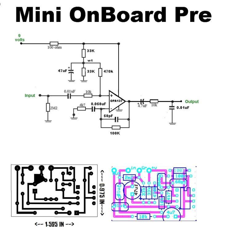
I have a simple design for Active electronics for your guitar if you want it....It fits a PCB about 1in x 1in square and runs off of a 9V battery....It uses a single opamp and the Feedback resistor can be adjusted to the ammount of gain you want or can be replaced with a Trim pot for adjustable Gain.....
I put this curcuit in my Crappy Epiphone Junior and it made a 500% differance and improvement to the tone....I actually brought the guitar over to my Guitarists place yesterday for him to try and he was totally ammazed because it blew away his $3000 Les paul and all of his other guitars, He has now got me doing a total redesign of the wireing of one of his guitars as well as adding active electronics to it so he can try to get the tone that my crappy $100 guitar has.....
If yer interested I"ll post the design for you....
Cheers
Hi,
Loved the idea of an awesome onboard preamp but fairly new to circuit building so had a few questions...
Does it matter what Op Amp you use?
Also for that layout what dimension of resistors and capacitors did you use?? - Im using Eagle and all the different component options are MASSIVELY confusing.
Would this work also work with an upright bass piezo pickup?
Many thanks,
Seth
Hi,
Loved the idea of an awesome onboard preamp but fairly new to circuit building so had a few questions...
Does it matter what Op Amp you use?
Also for that layout what dimension of resistors and capacitors did you use?? - Im using Eagle and all the different component options are MASSIVELY confusing.
Would this work also work with an upright bass piezo pickup?
Many thanks,
Seth
That particular design needs a Single fet input opamp , any one will do but it should be a Fet input one like OPA134 , OPA137 , TL071 ect .....
The resistors are all 1/4 watt which are all generally about the same size ..... The Electrolytic caps are generally all have a 3.5mm pin spacing but 5mm would also fit or most any modern cap in a 16v rating, the rest of the caps can be ceramic if you want, but I used 63v Film caps ...... just use what will fit .....
You will also need to get a TRS input jack for the guitar , you will need to wire it so battery gets disconnected when the Patch cord get pulled out (signal to tip , ground to sleeve, battery ground to ring) .....
This circuit would need to be Modified for a Piezo , I think if you change the 470k resistor to a 10m resistor then it would be more suitable for a Piezo .....
Cheers
Awesome, Parts ordered and on their way 
Just one question regarding the design..
I drew out the schematic in Eagle then converted in to the pcb using your layout. I thought it would be interesting and useful to input a schematic then make a board which I already knew the layout to so I could better understand how to efficiently populate a board.
Whilst doing this one of my connections didn't match up. The top of the 33k resistor (directly under the +v connection on the board) wants to connect to the ride hand side of the 100k resistor (2nd down from top right) ---- are these positions making sense? If not I can post a picture. ---- Im pretty confident this isn't a error on the board layout as you've already had success with this design. is this my error when inputting the plans into Eagle??
Also could you explain a bit more about the TRS wiring??
Thanks again so much for your time!
Seth
Hi all!
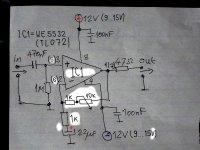
Here is simply a good schematic that can do the job!
IC1=NE5532; LF353; OPA2228 etc,...
The input resistor (1MOhm) connected to ground determines the input resistance preamplifiers. For example the violin ceramic pickup should have a value of 4,7 MOhm, for a guitar pickup from 1 .. 3,3 MOhm!
With the trimmer 10k or (1 ... 470k) raises the gain to preamplifiers.
Cheers!
Attachments
Last edited:
Also could you explain a bit more about the TRS wiring??
A TRS Jack socket has 3 contact fingers, it's often used for stereo signals, but in a guitar pedal only two are needed for the signal: the tip, furthest from the securing nut, which carries the 'hot' signal, and the sleeve, closest to the nut, which is ground.
The middle contact finger is the ring, as it appears on a jack plug. A guitar pedal switches battery power on or off according to whether a jack is inserted into the input socket by connecting the battery ground terminal, nearly always the -ve terminal (fuzz faces being an exception) to the middle, or ring contact of the socket.
When a mono, ie guitar type jack plug is inserted into the socket, the ring contact connects with the sleeve of the plug, completing the connection of the battery -ve to circuit ground, via the sleeve contact of the socket.
Slightly quirky, but universally used. Do it on the input socket, not the output.
- Status
- This old topic is closed. If you want to reopen this topic, contact a moderator using the "Report Post" button.
- Home
- Live Sound
- Instruments and Amps
- Discrete Guitar Preamp help