im wanting to make (from scratch or a kit im not fussed) a 2-channel preamp to feed into a 100watt torque poweramp to play my guitar through.
i want it preferably to have a clean channel and a dirty channel. the dirty channel should be really metal and crunchy like a high gain marshall on 11 or a dual rec.
also it needs a b,m an t eq on it as the poweramp has just a vol control.
schematics and links would be helpful.
any suggestions?
abe
i want it preferably to have a clean channel and a dirty channel. the dirty channel should be really metal and crunchy like a high gain marshall on 11 or a dual rec.
also it needs a b,m an t eq on it as the poweramp has just a vol control.
schematics and links would be helpful.
any suggestions?
abe
Plenty of suggestions, almost all guitar preamplifiers I've seen fill those terms, except the "metal and crunchy like a high gain marshall on 11 or a dual rec", which is the most important one.
My opinion: Build a clean preamplifier then make it have a switchable effects loop (i.e. selection between two individual FX loops) and stick with pedals. Most distortion circuits that really are adequate for metal tones are more complex than just fitting a couple of diodes to clip the signal. Take a look at Boss MT-2 for example: http://www.goldhand.com.pl/audio/gitara/efekty/boss_mt.gif
Besides that diode clipping you need a lot of proper filtering post and pre. If you build a simple circuit it will quite likely just sound bad - unless it is designed for a clean tone. And with "clean" I mean a lot of headroom, not something that will annoyingly clip to rails once you pluck the strings harder. Start from having a clean circuit, that is the main sound of your amp no matter how much distortion you decide to add afterwards. Concentrate on tweaking the tone stack circuit: It has the largest effect on amplifier's tone besides the speaker system.
Solid-state guitar preamps are basically easy to design, just few clean opamp stages with moderate or low gain, some high and lowpass filtering to remove unneccessary bass and excessive high end, then insert a suitable fender/marshall/vox/whatever tone stack in between. Add perhaps few extra gain stages or buffer circuits more for FX loop and reverb. If you want more headroom or supposedly rounder clipping characters replace opamp stages with jfets or transistors. They tend to cause more distortion (even when "clean"), although nobody will likely notice a difference. All those building blocks are common knowledge to anyone that possesses even a moderate knowledge of basic electronics. Well, perhaps not the tone stack circuitry - but that is quite common to people dealing with guitar audio. If unsure, just google for "tone stack".
Anyway, any distortion in solid-state designs aimed for guitar amplification should be caused intentionally. Usually this involves enhancing or attenuating certain frequencies and using high/low-pass filtering post/pre the overdriven/clipping part of the circuit. See the "Boss pedal" example. Simple designs will likely sound bad if you aim for metal tones.
More complexity comes from designing a suitable layout, switching arrangements between channels and other circuit parts (especially with solid state switching) etc. To this part most schematics really offer no help, except by giving you ideas, of course.
There are hundreds of guitar preamplifier schematics circling in the internet. I could post you links but it's not worth the trouble since you can find them very easily if you just search. Besides, I don't keep a track of links to schematics - I rather just save all interesting designs on hardrive for further studying. Anyway, building a preamp is just as easy as I described but making the circuit have a tone you like - especially a distortion tone.... well, I believe that no-one can tell you which circuit is good for that. Be prepared to tweak the design you choose.
If you want nice distortion tone, use a pedal or build a circuit that you know has a nice distortion tone - shouldn't be a big problem to implement it to a preamp design and make it switchable, if you know what I mean. In my opinion, having these circuits on a pedal plugged to switchable effects loop (or just between guitar and amp) means more versatility. The one day you get tired to that distortion tone you can easily change it without changing the whole amp, right?
Since you already stated one preference you could start by looking at Marshall's designs: http://www.drtube.com/marshall.htm See section solid state. Also, many of their modern designs (and some of the older ones as well) use solid-state preamps. Be prepared to browse through a lot of schematics. They do look complicated but that's what you get when you need channel switching or even mediocre sounding distortion tone. Still, basically all that those circuits contain are few gain stages with carefully selected low and hipass filters and a tone stack circuit. Runoffgroove site (http://www.runoffgroove.com) also contains some very nice sounding designs - basically intented as external distortion pedals. I recall there was a circuit mimicking Mesa amplifiers there. I see no reason why few mods and some extra circuitry for clean tones and channel switching could not turn any of these designs into a preamplifier you need.
You have a task of figuring out what a certain circuit part does to the sound. Otherwise you are just blindly building a design - and possibly you end up dissapointed afterwards. This is why I implicated that if you already prefer a certain tone, use a pedal or use the amp or whatever that has the tone or copy the circuit in it. Then, schematic is just a half way there... you have to design a layout etc.
i see.
i have found a jcm800 'emulator'. it uses jfets and mimics the whole amp not just the preamp so apparently it sounds rather nice. i was thinking of sticking with that as a clean(ish) preamp stage and using my boss me50 for the effects, which i was originally trying to avoid.
the thing that puzzles me about the jcm emulator is that it doesn't appear to have any clipping stages so the 'drive' must be purley overdriving the jfets. i've never heard overdriven jfets personally and i was wondering if it would sap the tone.
also, i found a 12ax7 fender emulator buffer thing also using a j201. would it be worth sticking this infront of the preamp for a bit more warmth - im a metalhead but i still like tone.
Clipping characters of both FETs, BJTs and vacuum circuits depend on the gain of the actual device, the gain setting of the circuit, DC bias point of the circuit, amount of negative feedback applied and, last but not least, on low and hi-pass filtering of the stage (post and pre). The tone of a certain device is always as much a result of the surrounding circuitry. Without seeing (and usually hearing as well) the actual design it's always difficult to comment anything about its tone, which is also a highly subjective matter:
I can tell you that I think the clipping characters of a common source JFET gain stage are not that superior over clipping characters of a transistor (or even an opamp) and some one else can tell you that they are. To my ears both clip suddenly and harshly - in circuits designed for clean tones. Then again, another common source JFET gain stage (or a common emitter BJT stage), designed to be overdriven, can sound good while clipping but to my ears it does not sound very good if I need a clean tone.
Don't believe all the hype about clipping characters of certain devices. There is some truth in it but in the end it all comes down to all variables I listed and to how they interact with each other. If you like the tone of a certain circuit then build it. It's that simple.
well ive got a lot of time on my hands so i might as well build the jcm preamp and fiddle with it a bit. i might havea crack at that tube clipping circuit from uncle jed. if none of it works ill bite the bullet and buy myself an amp.
tell me what you think of this schematic though.
tell me what you think of this schematic though.
Attachments
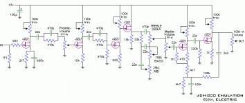
That is almost like the version of "Thunderchief" effect from runoffgroove.com that had a tonestack (http://www.runoffgroove.com/tc-tone.png). There are couple of differences - like an extra gainstage - but at least the mysterious "Electric" should have given credit to the original designers of this circuit. The low-pass filter is missing as well - that will make a difference to the tone.
There were some problems with the original design so Runoffgroove has released another updated version called "Thor", that is quite different from the original (http://www.runoffgroove.com/thor.html). The linked page discusses some issues related to the original design. You'd better read the FAQ (from the same site) as well since there is a question related to biasing problem of the old design - the circuit you linked has the same problem. There is also a mp3 sound link to the basic "Thunderchief" design that you might want to check out. I'd imagine the inclusion of another gain stage and tone controls will shape the sound quite drastically though, not to mention the exclusion of the lowpass filter.
This design has shown up earlier here at DiyAudio when someone asked how to convert it to higher (and dual) supply voltage. It was mentioned that the supply rejection of this kind of circuit is very poor and I completely agree with that. Unless you decide to run that thing from a battery or from a very stable regulated supply you need to add some filtering between stages to lower supply ripple and to prevent possible "motorboating".
yeah i was checking out runoffgroove earlier and i was mightily impressed with all the stompox amp emulators.
but now im stuck:
if the jcm 800 is as difficult as you say, i could just make a different preamp - the uno sounds great and is a clone of a boogie so it must be good.
the thunderchief sounds nice and crunchy also but apparently putting a tonme stack in it complicates it and they go wrong. the thor sounds ok but maybe a bit too limited.
i could even use something like the marshall eighteen watt emu so i can just use a clean sound on it and pump my pedal into it.
but the toss up i think is still between the jcm 800 (and if it doesnt work, accept it) and the mesa boogie mk1.
i guess the mk1 will have more chunk.
what do you think?
Nope, it's not the tone stack that causes problems. Apparently there are some problems in the gain stage that mimicks the phase inverter circuit and takes feedback from the output stage.
A direct quote:
"Too much resistance between source and ground will prevent the stage from functioning correctly. Reducing the resistance then re-bias, and the stage will amplify as it should. With different part numbers for the FETs (we've tried a few), you'll find some that will not work at all. Some will not bias regardless of the resistance you have between +V and drain. If however, you change the resistance between source and drain to something within the particular FET's "operating range," you'll be able to bias up and the stage will perform as it should. Apparently, even J201s are inconsistent enough to cause the circuit to work well for some and not for others."
True, FETs are very inconsistent and that's why those circuits have those trimmer potentiometers - and even they seem to go out of range sometimes. There seemed to be an easy fix to the problem that was described in the FAQ:
"Find the 470/4k7/4k7 resistor chain going from Q3 source to ground. Reduce the first 4k7 to something smaller. Try 1k, then re-bias to half the supply voltage at the drain."
There you have it. I don't think either Uno or Thunderchief are that difficult to build. If you have time you might as well build all of them, the cost of parts is extremely low and (considering future projects) you probably wish to buy a nice bunch of those FETs anyway.
I haven't built any of those circuits but based on the sound clips my personal opinions are: Uno sounded pretty nice on melodies that were played on high notes but I had a constant impression it would "fart out" on lower notes, especially if one plays damped riffs with power chords. Unfortunately the sound clip will not reveal us the truth about this. Anyway, you can hear the circuit rumbling pretty nastily in the beginning of the sound clip.
Thunderchief sounded OK but it didn't impress me. The tone was pretty dark and lacked some of that high end "bite" and "definition" that Uno had. However, this effect seemed to be more suitable for stuff played on lower notes. I guess it would sound nice when playing damped power chord riffs with occasional fills. I think the sound clip didn't do justice for this effect. Maybe the circuit had too much gain. I'm a metalhead as well but I prefer styles like black and dark metal. I guess this effect wouldn't cut it for that kind of tremolo picking or melodic stuff that needs a lot of high end and clarity. Coupled with the typical, atmospheric echo effect the Thunderchief would probably sound muffled and horrible.
The JCM800 emulator by Electric. No sound clip on that but this is how imagine it would sound like: The lowpass filter is removed so the sound is brighter than with the Thunderchief. Tone controls cause a scoop at middle frequencies and bring more clarity to the signal. They also offer more versatility when compared to Thunderchief or Thor. It has an extra gain stage, which is good considering insertion losses caused by the tone stack, but if the extra gain is not implemented carefully it might lead to excessive overdrive in one stage that causes the sound to "fart out" on bass frequencies.
Thor: No sound clip of this either. It has an SRPP stage ("mu-amplifier". Usually I would avoid using push-pull circuits in the preamp but this kind of circuit is an exception: SRPP has softer clipping characters than a conventional common source gain stage and also a plenty of gain. No comments on tone because I haven't heard this. The circuit has no tonestack, which is a big minus.
My personal pick out of the four would be "Uno". It has tone controls, a sensible amount of gain and it sounded pretty good for soloing or melodic stuff. If I'd ever build it I would definitely have to tweak that low end to make it sound better though. I consider this circuit as a good basis for further tweaking but as is I didn't find it's tone very impressive. I guess that all of these circuits would suck if I had to use them as the only preamplifier - I would definitely need a separate circuit for acquiring clean tones.
If you are planning to use one of these circuits as a part of a preamp be aware that higher rail voltage will increase headroom and you will loose the tone that you get with 9V supply. Also, as I mentioned the supply has to be stabile.
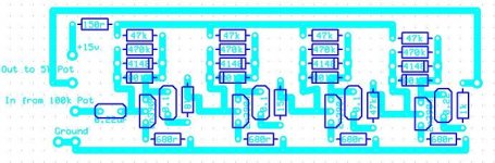
well i've just ordered a nice bunch of fifty j201s. i think i'll go for the uno mesa boogie thing as the angry channel and a fender or a tube screamer on low gain as a nice creamy channel 1. i'm topping it off with a switchable 'valve-sound' pre-pre-amp that's apparently based on a fender 12ax7 circuit.
i think it should be quite nice.
i think it should be quite nice.
Congrats on such a stimulating exchange.
At last, a really useful informative and intelligent discussion about design. My congratulations to all parties involved!
As an extra, seeing that tone stack calculation came into it, I wondered if this link would help anyone. It's a very useful tool to have on your PC.
http://www.duncanamps.com/tsc/index.html
Duncan Amps is well known of course, and the FREE (yes free!) tone stack calculator is really useful. You can choose a known style for starting point and change component values on the fly. The response changes will be mapped on the graph for comparison. Really useful to anyone designing their own preamp and who doesn't use a full Spice setup.
Thanks again.
metal preamp?
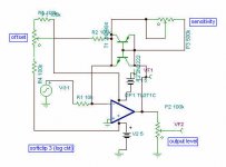
Hi I designed this preamp based on classic designs, but modified to provide extreme gain it uses 1 ECC82 and 2 ECC83 valves, it is part of an hybrid amp.
In the zip file you will find the preamp schematic, I have a short sound clip if you want it I can send it to your mail
Hope it suits your needs if you build it feel free to send me your questions or comments.
Regards.
Attachments
Here is an op-amp pre-amp design that I worked on for my young son a few years ago. It may be of some use to you. His mate had a Fender front-man so he needed something to compete. It was coupled to a 25W chip amp. I had it at the stage of a working prototype built as a combo (still have the fully built board somewhere) when my son decided that he preferred the sound of valves and went back to the 7W all valve combo I had built earlier... so end of project. This is a preamp only. 2 inputs so one of his mates could plug in as well. Tremelo on both channels and switchable distortion/clean on the second channel. Distortion has gain and tone controls. Has a 3 band active eq, that from memory needed some work on the component values to work in the guitar range, especially the treble. I had some capacitor values worked out but can't recall what they were. A dual supply +/- 15v is needed. The 50hz notch filter intended to combat single coil hum was dropped from the final design. Channel switching was done by a relay on the main board. Ldr1 and led1 were coupled together with black plastic tubing for the tremolo. Its important to block out ALL ambient light from the led1/ldr1 setup, ie ambient light comming in from the back of the led will affect the tremolo, even the shadow of a person walking past the back of the combo will affect the tremolo. ldr1 is one of the cheap Dick Smith types about 6 or 7 mm in dia. Led1 is high intensity red led also from Dick Smith. Led2 and led3 are part of the tremelo oscillator. Fx in and Fx out were not used so I soldered a jumper between them on the board. This is all of the info that I have, but a few nights spent studying the circuit and board layout and you should have no problem working out the function of the unmarked pots , connectors and IC's. Board was made using press and peel. I made the mistake of assuming that it was A4 size when in fact it is US letter size so I had to shrink the final printing using the printer properties, from memory I think its about 95%.
Input sockets were placed in the gaps between the channel volume controls with short lengths of sheilded cable running from the sockets to the board. The thin lines on the board are jumpers, I spent many hours trying to get a single sided layout with no jumpers, but in the end decided I had already spent enough time and had to be content with the board as you see it. Circuit is put together from smaller circuits I found in magazines and on the net, they are all standard text book stuff. Mine worked first time the only problem being the tone controls which worked backwards. I had to cut tracks to fix the problem. I'm not sure if the board here has the same problem but its easy enough to fix by cutting tracks and basically swapping the two ends of the pot connections using short lengths of wire, or you could re-route the tracks before the board is made using some sort of graphics software. Its not fancy but it has been built and tested, it works.
http://www.megaupload.com/?d=SVKY99C9
Board and circuit are PDF files located on Megaupload. Sorry for using Megaupload but I could'nt make the files small enough to include in the post. If you don't know how to use Megaupload just cut and paste the above link into a browser address bar and press enter, The megaupload page will start, you may have wait while a timer counts down, could be up to 1 min You will be shown a picture of some text (usually 3 letters) just enter these letters into the box provided and press enter. Download should start.
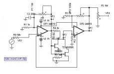
I am useing this curcuit in my Guitar amp for Distortion and it is honestly one of the Best distortion sounds I have ever heard.....
The design calls for 2n3904 Transistors but I found I get a MUCH better sound useing 2N2222 Transistors....
If you want to use it as a Pedal you could easilly add a Bypas switch so you can Turn it on a off by stepping on the Bypass switch and best of all it will only cost about $4 in Parts at most....
I play Heavy death metal and hardcore Punk type music and this is perfectly suited for this type of Music.....
Cheers
PS: the orentation of the Transistors is reversed in the diagram....
Attachments
- Status
- This old topic is closed. If you want to reopen this topic, contact a moderator using the "Report Post" button.
- Home
- Live Sound
- Instruments and Amps
- solid state metal preamp