I've done a Fuzz face with this schematics:
BUT IT DOESN't WORKS!!!
The effect is just passing a signal trought(actually sound gets a bit muddy) and i can't get a distorted tone. I used AC188 germanium PNP transistors.
Here are the pictures:
If you guys can help me that would be awesome.
An externally hosted image should be here but it was not working when we last tested it.
BUT IT DOESN't WORKS!!!
The effect is just passing a signal trought(actually sound gets a bit muddy) and i can't get a distorted tone. I used AC188 germanium PNP transistors.
Here are the pictures:
An externally hosted image should be here but it was not working when we last tested it.
An externally hosted image should be here but it was not working when we last tested it.
An externally hosted image should be here but it was not working when we last tested it.
If you guys can help me that would be awesome.
Just a couple of things, without actually tracing out the circuit:
1) Note that this is a positive-ground circuit, which is unusual by modern standards. Make sure you've got the + side of the battery (or power supply) connected to ground.
2) Are you sure that's a 100K resistor next to the transistors? It looks (on my monitor, at least) like the multiplier band is red, which wouldn't be right.
Reid
1) I've done this.
2) Multiplier is orange. Have you compared the color with 8,2k tranzistor (which has two red bands)?
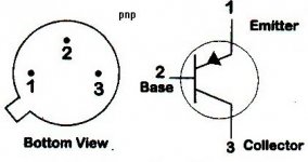
is this correct connection of the transistors???
When I'll know how to connect transistors, i'm going to make it with PCB.
2) Multiplier is orange. Have you compared the color with 8,2k tranzistor (which has two red bands)?
is this correct connection of the transistors???
An externally hosted image should be here but it was not working when we last tested it.
An externally hosted image should be here but it was not working when we last tested it.
When I'll know how to connect transistors, i'm going to make it with PCB.
An externally hosted image should be here but it was not working when we last tested it.
Starting with the tab, going clockwise, the legs are E B C. It looks like you may have the emitter/collector reversed. base looks ok. let me know how it ends up sounding, maybe i'll build one too (if you ever get yours to work
") )
)where'd you get the transistors, they are vintage, no?
jancooo said:2) Multiplier is orange. Have you compared the color with 8,2k tranzistor (which has two red bands)?
Of course I did, but not all resistors use the same shades of color. (Look at the difference in the brown on the 100K and the brown on the 470, for example).
Speaking of brown... since the two visible bands are brown and (now I know) orange, it can't be a 100K resistor, so what is it? If it's much too low, it could cause the signal to be low and undistorted by passing too much negative feedback current to Q1. If it's 91K (white brown orange) it's probably close enough.
If the pinout posted by elementx is right, then he's correct that you've got the emitter and collector swapped. (His diagram is missing the arrowhead on the emitter.) Have you tested the transistors and measured the gain on them?
Reid
To me it looks like the 100k (brown, black, yellow) resistor is 10k (brown, black, orange), and the 33k resistor might be 2.2k. I could be wrong; as you say, red and orange can be hard to differentiate.
But we shouldn't be guessing this. Get youself a multimeter and measure! Doing electronics without one is like bird-watching without binoculars: possible, but very error prone.
Rune
But we shouldn't be guessing this. Get youself a multimeter and measure! Doing electronics without one is like bird-watching without binoculars: possible, but very error prone.
Rune
pnp
the pnp ac188 is great gremanium transistor!!!!!!!!!!!!!! i have few of them
you just got the collector and emitter mix up
after that should work great
you only reverse the pins for pnp transistor
if had ac187 it would be way the schematic show
you might wana get some transistor sockets sometimes the heat form solder can damge them
Attachments
Test the transistors. All you need is a battery, two resistors and a meter, and you'll know not only if they're good, but how much gain and leakage they have.
Here is a useful page.
Reid
Here is a useful page.
Reid
transistor testing
or you could use a multimeter with a transistor test socket
just an example http://cgi.ebay.com/3-1-2-LCD-Multimeter-AC-DC-LCR-Frequency-hFE-diode_W0QQitemZ300052305536QQihZ020QQcategoryZ66991QQssPageNameZWDVWQQrdZ1QQcmdZViewItem?hash=item300052305536
it say transistor testing
i know thiers other way but i use
- Status
- This old topic is closed. If you want to reopen this topic, contact a moderator using the "Report Post" button.
- Home
- Live Sound
- Instruments and Amps
- Fuzz face problem