I think it unlikely, but does anyone have a schematic for this amp, ('cause it looks sweet)?
http://www.drzamps.com/route66.html
Specifications:
Power Output: 32 Watts
Output Tubes: 2 - KT66
Preamp Tubes: 1 - EF86, 1-12AX7
Rectifier: 1 - GZ34
Controls: Volume, Treble, Bass
Configurations: Head
Colors: Black. Other custom wood finishes are available
Dimensions: 17 1/2" W, 9 7/8" H, 9 1/2" D
Weight: 22 lbs.
General Info:
"The Route 66 is an all original Dr.Z design based on the incredible KT-66 tube originally built by Genelex. This tube generates the "Milkshake Thick" tones, as heard on John Mayalls "Bluesbreaker" album featuring Eric Clapton (the "Beano Album" as it is known to many).
This is not a duplicate of the Marshall JTM-45, but completely original spin with new tonal end results. The "Route 66" has a EF-86 front-end. For those not familiar with this tube, it is a 9 pin pentode , offering incredible gain and input dynamics. It is normally used in high-end stereos, most often for its accurate transfer of input signal, balance, and headroom.
The amp features a deceptively simple tone stack, consisting of Volume, Bass, and Treble, which feeds a non-negative feedback Phase Inverter, for true harmonic content and full output tube dynamics. It has a GZ-34 Tube Rectifier to complete the round enveloped tone. The amp has piano-like clarity with endless sustain, even at low volumes. Its 32 watts truly sing when driven hard in a focused, thick distortion, with the tightest bass response you've ever heard."
Actually I don't think it is exactly like the Mullard 5-20, first of all having designed a few guitar amplifiers for a living I believe that the tone stack is interposed between the EF86 and the 12AX7, secondly it is clearly mentioned that the amplifier does not use feedback back to the phase inverter.
I would try running the EF86 in current starved mode for the most gain possible. In this application the volume pot on the guitar is probably going to determine whether or not you overdrive the EF86 and by how much. Place the master volume (1M ohm pot) after the tone stack. The master volume will determine by how much you overdrive the power amp when desired.
A very common guitar power amplifier topology is a long tailed pair driving a pair of tetrode/pentode connected output tubes. In this case because feedback is not used I would assume some extra care has been taken to assure good balance on the plates of the LTP. Plate resistors vaues would be chosen for highest possible gain, and might differ to assure approximate balance in the driver stage.
Not unlikely that fixed bias was used on the output stage. Bias resistors would be as high as allowed for this topology. I'd go for 220K resistors and limit dissipation to less than 25W.
Coupling caps should be sized to reduce the likelyhood of blocking distortion and might range from 0.015uF - 0.047uF max. Tetrode connection most probably and right off of the B+ at the point feeding the output transformer. (There are a few UL connected project guitar amps, but I have not heard one recently. UL might be better for damping in the context of an amplifier without overall feedback. I 'd try it both ways frankly.)
Power supply probably not very stiff using something like 32uF input filter cap max. (my guess commonly available JJ cap or similar would be used.) I'd aim for right around 400V under quiescent conditions
The tone stack would most likely be modelled after the Fender/Marshall stack (nee Western Electric)
The tone stack calculator software at Duncan Amps should help you to design an appropriate tone stack.
These are best quesses on my part, reading between the lines in the marketing copy. Small companies sometimes give things away in their marketing copy if you look closely enough.
As always YMMV, and good luck!
Thanks
According to this:
http://en.wikipedia.org/wiki/Mullard_5-10
The Mullard 5-20 was the one using the EL34.....
According to this:
http://en.wikipedia.org/wiki/Mullard_5-10
The Mullard 5-20 was the one using the EL34.....
peritus307 said:Thanks
According to this:
http://en.wikipedia.org/wiki/Mullard_5-10
The Mullard 5-20 was the one using the EL34.....
lol.. I just noticed this was already posted...


kevinkr said:Hope you find my reply useful, I am just curious enough at this point that I could probably be persuaded to do a tentative schematic, although I owe one on another thread I need to do first.
Been of much help! Thanks
You needn't make a schemo, though... I'm really just casually looking into the design of the amp, from the perspective of my other thread needing an influence:
http://www.diyaudio.com/forums/showthread.php?s=&threadid=90325
I'd use the carillon amplifier chassis to build one of these or just grab the power tranny. The opt is not going to be of any use. I'd expect a flame fest with that one in a guitar amplifier app, just too puny. Carillon amps are low duty cycle. I listen to carillon almost every day at Chautauqua during my summer visits - not exactly overtaxed.
Good luck.
Good luck.
kevinkr said:I'd use the carillon amplifier chassis to build one of these or just grab the power tranny. The opt is not going to be of any use. I'd expect a flame fest with that one in a guitar amplifier app, just too puny. Carillon amps are low duty cycle. I listen to carillon almost every day at Chautauqua during my summer visits - not exactly overtaxed.
Good luck.
Can you assist me in evaluating the power tranny? I'm admittedly unlearned on this subject.. My main question is, when I'm done, will I still have a 35 watt amp? Is it all based off the tranny? Or is it rated by the tube choice or circuit design in general...
I can certainly provide some guidelines, in general the choice of power transformer, output tubes, operating point chosen and output transformer dictate output power available.
You should be able to get something in the ball park of 35W depending on choices made.
IMO a tube rectifier is the best choice for most guitar amplifier apps, does this transformer support that. (5AR4, 5U4 or whatever in carillon amp?)
You should be able to get something in the ball park of 35W depending on choices made.
IMO a tube rectifier is the best choice for most guitar amplifier apps, does this transformer support that. (5AR4, 5U4 or whatever in carillon amp?)
kevinkr said:I can certainly provide some guidelines, in general the choice of power transformer, output tubes, operating point chosen and output transformer dictate output power available.
You should be able to get something in the ball park of 35W depending on choices made.
IMO a tube rectifier is the best choice for most guitar amplifier apps, does this transformer support that. (5AR4, 5U4 or whatever in carillon amp?)
No... I've got
2 x 6L6GC's
3 x 12AX7's
1 x 12AV6
I need to research transformers, in general, more... I'm going to post a better description of the transformers ASAP....
Thanks
I found this somewhere, but I'm not certain of its accuracy. It is similar to a Mullard circuit, but has no feedback, fixed bias and a tone stack between the input pentode and splitter. The treble control on the tone stack looks like it's wired backwards. It looks like a good starting point for a guitar amp, but I would experiment with the 6.8n bright cap on the volume control if it sounds too harsh
Attachments
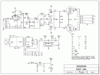
kiwiandy said:I found this somewhere, but I'm not certain of its accuracy. It is similar to a Mullard circuit, but has no feedback, fixed bias and a tone stack between the input pentode and splitter. The treble control on the tone stack looks like it's wired backwards. It looks like a good starting point for a guitar amp, but I would experiment with the 6.8n bright cap on the volume control if it sounds too harsh
Looks very similar to what I was thinking. The tone stack is a bit odd, but I believe the treble control provides cut against the 6.8nF cap in the volume control circuit. The effect of that cap is less as the volume control is turned up. A bit odd, but the guy is well respected in terms of amplifier design and may know a thing or two about voicing his designs that we don't ..
kevinkr said:... the guy is well respected in terms of amplifier design and may know a thing or two about voicing his designs that we don't ..
That's putting it mildly!
-- Dave
- Status
- This old topic is closed. If you want to reopen this topic, contact a moderator using the "Report Post" button.
- Home
- Live Sound
- Instruments and Amps
- Dr. Z "Route 66"