I'm working on a tube-hybrid gainclone guitar amp. I figure that by using a tube guitar amp fed into a Gainclone instead of an output transformer, I can get "tube" sound without most of the cost.
You can se the progress in the Gainclone forum here:
http://www.diyaudio.com/forums/showthread.php?s=&threadid=87279
Helpful as the GC people are, most of the people in the forum are (not surprisingly) trying to avoid distortion. With guitar amps, "tube" distortion is what makes them desireable.
Any suggestions on how to do this? The AX84 looks like a good starting point; hopefully, with a voltage divider on the input, I can feed it in directly. If I scrap most of the parts from another amp, I can keep the cost of the tube stage to under 40$. (20$ for tubes, 20$ for the rest - and it's not a complex amp!)
Have you considered the obvious/easiest, building a tube distorion/overdrive like the McTube and just putting it in front of the GC stage?
Your question is too broad otherwise; what do you want the tube stage to do? Just add tube clipping sound? Tone controls, presence, etc., are needed too?
Your question is too broad otherwise; what do you want the tube stage to do? Just add tube clipping sound? Tone controls, presence, etc., are needed too?
leadbelly said:Have you considered the obvious/easiest, building a tube distorion/overdrive like the McTube and just putting it in front of the GC stage?
Your question is too broad otherwise; what do you want the tube stage to do? Just add tube clipping sound? Tone controls, presence, etc., are needed too?
The tube amplifier stage I'd like to use is a complete tube amplifier, with both halves of a 12AX7 and an EL84 or 6V6 being used as an output tube.
http://annex.ax84.com/media/ax84_m311.pdf
Now, here's what I would hope you could clear up.
(Please refrain from laughing.)
From what I understand, the output transformer is to drop the super-high-impeadance output of a tube to the low-impeadance ouput needed for a common 4- or 8-ohm speaker.
A stock Gainclone is pretty high-gain, and would likely be driven into clipping by the output of the EL84. Gainclone clipping sounds nasty. I'd like to try preventing this by using a high-impeadance (Ground<-2k ohms->input<-8k ohms>Gainclone) voltage divider to drop the input far enough that it would'nt clip. Although I might lose some power, 30 quality watts is all I'm really looking for. (Besides, bridging Gainclones is easy!)
leadbelly said:OK, but then what are you asking; you have already decided on a very specific design, where's the question?
Actually, I have'nt. From what I've heard, the output from this amp will blow the gainclone. This is bad.
However, I think I found the solution: A 1/2 watt push-pull amp.
http://www.firebottle.com/ampage/schems/moonlight.gif
It's a 1/2 watt push-pull amplifier. Could it be converted to a class-A amplifier? If so, I could build two discrete amps, each using half of two tubes. (Woot!)
Also, can anyone reccomend some (preferably cheap) tube diodes? A 1/8 watt amp likely does'nt need much power, so a tube diode is economical.
As an added bonus, it likely won't blow up the gainclone.
You're throwing out a lot of things there.
Why would the amp blow the GC? Keep the input voltage below 40V by the required voltage divider, set up the GC as a unity gain buffer, and you're done.
Why do you care about Class A? You are trying to add distortion.
Why do you care about a tube rectifier? Economical? No way you can buy even a used tube and used socket for less than a few SS diodes.
Hi,
If I understand you correct, you want a full tube amp, minus output transformer, driving a gainclone?
If this assesment is correct, it's not only not-loco, but has been done. Carver used an EL34 to drive a MOSFET stage, through a tranny though.
You want to keep it simple, economical and no tranny.... no problem!
Parafeed the final tube with one of them diyAudio HV PNP CCS's and cap-couple it to your resistor divider and drive your gainclone")
If I understand you correct, you want a full tube amp, minus output transformer, driving a gainclone?
If this assesment is correct, it's not only not-loco, but has been done. Carver used an EL34 to drive a MOSFET stage, through a tranny though.
You want to keep it simple, economical and no tranny.... no problem!
Parafeed the final tube with one of them diyAudio HV PNP CCS's and cap-couple it to your resistor divider and drive your gainclone
leadbelly said:You're throwing out a lot of things there.
Why would the amp blow the GC? Keep the input voltage below 40V by the required voltage divider, set up the GC as a unity gain buffer, and you're done.
I don't think that the most commonly used LM series chips are unity gain stable. You'd have to make sure to find one that is.
Geek said:Carver used an EL34 to drive a MOSFET stage, through a tranny though.
This should be just as easy as using the chip amps, but as Geek said, without the tranny. The chips have lots of front end stuff you don't need. On the plus side, they do have some built in protection. Check www.tubecad.com for some simple tube fed Mosfet output stages.
Sheldon
See if you can get member Tubelab to weigh in here. He does audio and guitar amps, with and without sand. Bet he has some ideas.
Geek said:Hi,
If I understand you correct, you want a full tube amp, minus output transformer, driving a gainclone?
If this assesment is correct, it's not only not-loco, but has been done. Carver used an EL34 to drive a MOSFET stage, through a tranny though.
You want to keep it simple, economical and no tranny.... no problem!
Parafeed the final tube with one of them diyAudio HV PNP CCS's and cap-couple it to your resistor divider and drive your gainclone
Can you explain the last sentence in more easily understood english?
The reason I suggested the tube rectifier for the tube stage is that tube rectifiers do odd things when overloaded. Because the amplifier is pushing a ridiculously small amount of power, I can use a cheap-0 tube diode.
As for the Class-A on the amp, I was hoping to reduce the power even further, and build two amps into one. Adding gain to a Gainclone is easy, and adding a second Gainclone is even easier. Using each side of the amp seperately with two different Gainclones and drivers would allow for a stereo amp. That said, you're right; I think I'll leave it as a push-pull amp.
Hi,
Ok, sorry about that.
There is a thread here for SS constant current sources/sinks
http://www.diyaudio.com/forums/showthread.php?s=&threadid=72740&highlight=
I suggest this for the parafeed final stage because it eliminates the need for an expensive inductor, or transformer. An example of parafeed amp can be found in an application note I wrote for this board, found here:
http://homepage.mac.com/tlinespeakers/FAL/downloads/AppNotes-0.2_HV_PNP_CCS.pdf
But instead of a transformer, use a resistor load equal to the required load from a transformer. You can use two resistors in series for the load, setup as a divider so you don't overload the gainclone.
There was a discussion on this idea some time ago. I came up with an idea which I think is superior to the use of a voltage divider for the tube stage and is still cheap.
Firstly - make absolutely certain that the gainclone never clips. This will sound horrible.
Second - use solid state rectifiers and place resistance in series with them, they will behave in prity much the same way as tube rectifiers as the main difference between tube and solid state is their impedence. You will get the rail sag you are looking for.
Thirdly - use a parafeed interstage transformer to drive your gainclone. This will take care of the step down. This has a number of advantages. Namely it will introduce transformer distortion which is the main characturistic which makes a quitar amp sound as it does( along with speaker distortion). A small amount of DC can be introduced into the primary to encourage transformer satuation. This can be controlled by a wire wound pot from the HV rail. The transformer will perform better the cheaper and smaller it is, this is because it will have more High frequency and low frequency roll off. It can be a mains power transformer.
Fourthly - take the trouble to introduce a Marshell style tone stack.
Use back to back transformers for a cheap power supply.
The bottom line is that a simple tube preamp will never distort in the way that you want it to, and quite frankly you are waisting your time. People have done it and have never reported great results.
My idea is in the design and breadboard stage. Will be a few months before I have any results.
Hope that helps.
Shoog
Sheldon said:I don't think that the most commonly used LM series chips are unity gain stable. You'd have to make sure to find one that is.
I'm shocked at how often this is regurgitated on the board; it is simply not true.
http://www.diyaudio.com/forums/showthread.php?postid=112061#post112061
leadbelly said:
I'm shocked at how often this is regurgitated on the board; it is simply not true.
http://www.diyaudio.com/forums/showthread.php?postid=112061#post112061
You caught me regurgitating. I'm sorted on that one now.
Sheldon
Spasticteapot said:Could someone explain what Parafeed is?
Also, what if I were to take a cheap 1:1 signal transformer (they sell them at RadioShack) and use it in place of the reccomended output transformer on the Moonlight amplifier shown above?
There's a good explanation here: http://members.aol.com/sbench/outstru.html This time, I'm regurgitating an expert. Note that you can use either an inductor loaded tube or a resistively loaded tube with the same type of transformer. The key point is that the transformer is coupled through a capacitor, so that it sees no DC. This allows a smaller transformer, and/or, as Shoog suggests, you can add an adjustable external DC source to have controlled saturation.
Sheldon
Because your not asking the transformer to deliver any significant power, you can choose your output tube such that you can resistively load it. I did this with a headphone amp (using an ECL82) and used a 3K5 resistor as the plate load. Works well and is simpler than a choke or constant current source load.
Shoog
Shoog
Shoog said:Because your not asking the transformer to deliver any significant power, you can choose your output tube such that you can resistively load it. I did this with a headphone amp (using an ECL82) and used a 3K5 resistor as the plate load. Works well and is simpler than a choke or constant current source load.
Shoog
Well, I think I understand it. Here goes!
1. A tube puts out DC, but with a sine wave.
2. The inductor or resistor applies a near-constant voltage, without shorting out the tube.
3. AC is the end result.
RadioShack sells cheapo 1:1 signal transformers, and I can get quite a few more off of old modems. Many have high impeadance on at least one of the windings.
By adding some additional voltage to both sides, a DC offset can be created, saturating the transformer and causing distortion.
(My brain hurt now!)
So, how do I apply this to a (simple) guitar amp design like the Skylark, and how do I build a Marshall tone stack (whatever the heck it is?)
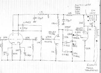
Shoog said:The schematic, untried.
Shoog
Neato!
What kind of output voltages can I expect?
- Status
- This old topic is closed. If you want to reopen this topic, contact a moderator using the "Report Post" button.
- Home
- Live Sound
- Instruments and Amps
- Help wanted for a truly loco project. (A Tube--gainclone hybrid guitar amp!)