I decided it was time to leave Zafira's thread alone. I aplogize for the massive hijacking.
My preamp now consist of a tube gain stage with a Svetlana 6N1P, wich will probably be connected to my BUF634 buffer through a potentiometer so I can set the level into the buffer. A little addition I thought up yesterday is a vu meter. I will use 3 pcs of LM3915. Since my preamp will be capable of fairly large output voltages I would like a way to:
1. Find a normal 0dB point
2. Know when I have overdriven the buffer into clip level
Do you think I should use 2 different meters or can I find a way to combine everything in one 30 led array? What should I use as 0 dB if i want it to be compatible with other gear?
I have finished my eagle schematics. Im still not sure about the values for P1 and P2, escpecially P2. I have run some tests where I had a 100k pot insted of 500k and I cant notice any difference. The cap banks C3 and C4 is made up of small tantalum bypassed by ceramic and will be placed VERY close to the buffer. Please let me know what you think.
Attachments
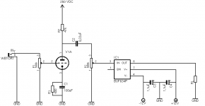
Is there any advantages with a B+ of 400VDC instead of 250VDC? Im fiddling around with duncan psu designer. Im going to order mains transformer and one or maybe two chokes soon. When it comes to the chokes... is it better with a higher inductance rating?? I have measured the current and its only 3.04mA so I have been looking at a 20H hammond choke that is very cheap.
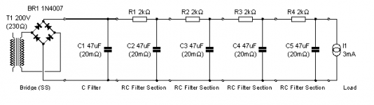
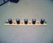
Today I have finished the CRCRCRCRC-filter PCB and I have tried it with my new Hammond 260A transformer. My voltmeter changes between 249 and 250 VDC so I am very pleased with the result. I have not made any ripple measurements but I think it should be somewhere near what I have simulated since everything else seem to match.
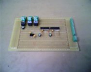
I have also soldered a few caps to my big PCB that will contain my buffer stage and VU meter complete with rectifiers and voltage regulators and all.
I have also soldered a few caps to my big PCB that will contain my buffer stage and VU meter complete with rectifiers and voltage regulators and all.
Attachments
Project progress
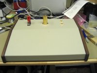
I have just started to drill holes and such in the chassis. Here is a little pic of the work so far. I will probably have two large knobs for input and outout level on the sloped face plate, and the input connector on the front part of the chassis. The idea is to have a 20 LED vu meter in the middle of the face plate.
I have just started to drill holes and such in the chassis. Here is a little pic of the work so far. I will probably have two large knobs for input and outout level on the sloped face plate, and the input connector on the front part of the chassis. The idea is to have a 20 LED vu meter in the middle of the face plate.
Attachments
- Status
- This old topic is closed. If you want to reopen this topic, contact a moderator using the "Report Post" button.
- Home
- Live Sound
- Instruments and Amps
- Hybrid bass/guitar preamp