Hi!
With some great help from this forum (here’s a link to my previous post http://www.diyaudio.com/forums/showthread.php?threadid=78015 I did a few mods to a tube amp head which is almost identical in appearance, layout and design to the Fender Blackface Tremolux Head. The mods were aimed to turn one of the amp’s channels into “overdrive channel” and to reduce hum and noise. I tried almost every hum and noise reducing technique, of which I was able to find information in this forum and the net, but with little success. The unchanged channel’s noise remained the same but is bearable. The “new” overdrive channel’s hum and noise are excessive and this is causing a great discomfort to my poor tone-loving soul. . I’m almost out of ideas. Please HELP if you can.
This experiment I did may be a clue for identifying the hum and noise source:
1. When I unplug the amp’s cable from the wall socket, it continues to play for about 6-7 seconds without ANY hum or noise whatsoever.
2. When I switch off both the power and the standby switches, the amp continues to play for about 6-7 seconds, but the hum and noise remain (decrease along with the signal).
3. When I switch-off the “standby” switch only (which cuts the HV supply to all tubes but leaves on the heating and the 50VDC power tubes bias) the amp plays only for less than a second (it’s more like a fart) and I can’t tell if there is noise or not. I have no explanation why in the above described cases the amp plays for a few seconds and in this case it goes quiet almost immediately.
Here are some other clues and notes:
• When I turn the “power” switch on (tubes heating and 50V bias only are "on") I can hear some low freq hum in the speaker. It’s almost non-audible and I really have to be very close to hear it, but it’s there. The PT is making some noise itself, but again, I have to practically put my ear on it to hear it.
• When all volume pots (a have a sep. volume pot for each channel and a master volume) are turned town, the amp is quiet, to the exception of the hum described in the previous paragraph but a bit louder.
• Even when the guitar is unplugged (thus the input is grounded), turning up any volume pots still produces quite hum and noise, more or less, depending on the stage for which the pot is used. The noise is not the “hiss” usually associated with pots, but an ugly mix of hum and noise,
• Plugging a guitar in does of course increase noise a lot (all else being the same) but not all that much, leading me to believe that the problem is not the guitar’s pickups, wiring or cable (one of my guitars has EMG 81 which is super quiet active bridge humbacker and the other has a passive humbacker which is as quiet as the EMG).
• By playing with the pots and by grounding the signal path here and there, I came to believe that each gain stage adds its share to the overall noise, the input stages (the first half of ECC83 and the also the guitar pickup – which could be viewed as a gain stage too) being more sensitive and contributing more noise than the latter stages.
Here’s a description of what I’ve tried so far with minimum to none results in terms of hum and noise reduction:
• Tried switching around and replacing all preamp tubes – no change at all
• Star grounded the whole amp, except for two of the power tubes grounds which are connected to the chassis - no noticable improvement
• Tried to use as short leads for parts as possible and ended up with some sort of ptp wiring - no improvement
• Used shielded wire for the first gain stage to the isolated input jack, to the overdrive pot and back, as well as to the tone stacks and back. The shields are connected only to one point - the ground for the corresponding section, usually the PS filter cap ground - no improvement
• Replaced all plate, grid, and cathode resistors in the preamp, as well as all tone stacks resistors with 0,6W Metal Film. I’m not sure of their voltage rating but the seller “assured” it’s sufficient, plus I’ve used the same resistors before in very quiet DIY tube preamps running at appx. 300V versus about 365V to 425V in my current project. So I wonder, what happens if the resistors in a tube amp are not rated for its voltages, can it be the cause of excessive hum and noise? (hmmmm – the amp was noisy with the old resistors so probably this is not it)
• For DC blocking, cathode bypass and signal attenuator caps in the preamp sections, I used WIMA MKP1/630V polypropylene caps - no improvement
• I made no changes or part replacements in the phase inverter and power amp sections
• Replaced the PS filter caps – no improvement
• Added in series a total of six 2k7 wirewound resistors and also new 33uF/450V filter caps decoupling the PS of each preamp gain stage - no improvement
• Tried placing very large resistors (39k to 68k) in the PS filtering RC network. No results despite the voltage drops.
• Disconnected the choke which was used for B+ to the OT and used it for B+ for the preamp section. No result, so I connected it back as it was.
• Tried DC bias of the 6.3V/AC filament supply – removed it, as it had no effect.
• I tried heating the first two tubes (four gain stages) with regulated 6.3V/DC (used a separate transformer). There was some improvement, but so small that I decided not to try providing regulated DC heating for the remaining tubes as it seems unpracticable.
So, I’m down to the following few mods I haven’t tried yet and most of which are associated with buying hart to find and expensive parts.
1. Put 10ohm/1W resistor across each rectifier diode – somebody in the forum suggested these will take care of voltage peaks from PS filter caps.
2. Get a suitable choke that can handle and filter the B+ for all tubes
3. Buy a 1:1 transformer to help clean up whatever is it that comes from the electricity grid and dares plaguing my sound. .
4. Try to heat all tubes with a car battery and if this helps, get a separate transformer and make a regulated 6,3 or 12,6 VDC for all tubes’ heating.
5. Regulate also the HV. (I suspect this may ruin the sound of the amp)
What do you think of these “last options”? Any other ideas!
I’m also currently tracing and drawing the complete schematic of the amp, but will probably not finish it until next week. I’ll post it, if anybody at all responds to my call for help and needs the schematic. Here’s a link to the schematic and layout of the Fender Tremolux which is almost the same amp http://www.schematicheaven.com/fenderamps/tremolux_ab763_schem.pdf
Thanks & sorry for the post being so long
Sounds like the source of hum is somewhere in the early stages of the preamp since you can control it's amplitude with gain/volume potentiometers. Then it is just gradually amplified throughout the various gain stages. This you have actually already figured out. Unplugging the amp will break the mains ground path - leaving it plugged in to the mains but powered off may not - this is the case at least with SPST mains switch. This might explain why no noise occures when you pull out the mains plug. This leaves me wonder what way the chassis grounded, does the amp have a three-prong coord?
A photograph showing the layout/wire dressing might be helpful. Here's few things you might want to investigate: Insulating jacks from the chassis - or are they already - are there some high current wires running near the preamp sections, the mains/chassis grounding scheme, use of separate audio/power ground paths.
Teemu K
1. Put 10ohm/1W resistor across each rectifier diode – somebody in the forum suggested these will take care of voltage peaks from PS filter caps.
This will do nothing useful and will likely blow something up, quite possibly your power transformer. Don't shunt the diodes!
2. Get a suitable choke that can handle and filter the B+ for all tubes
Possibly. If you do this, put another cap on the other side of the choke (shunt cap - series choke - shunt cap) of at least as large a value as the one on the input side. For that matter, you could just beef up the cap on the input side wthout adding a choke.
3. Buy a 1:1 transformer to help clean up whatever is it that comes from the electricity grid and dares plaguing my sound. J.
Expensive and unlikely to work.
4. Try to heat all tubes with a car battery and if this helps, get a separate transformer and make a regulated 6,3 or 12,6 VDC for all tubes’ heating.
Maybe, but try other things first. This is a pretty drastic step.
5. Regulate also the HV. (I suspect this may ruin the sound of the amp)
It probably won't ruin the sound of the amp. Your supplies want to be stable. However, it is a lot of work. Going with a passive filter (as in option 2 above) is easier, and you can probably get almost the same improvement.
One other thing you should try: make sure that the power transformers are not coupling flux into the output transformers. Try to keep them far away from each other, or at the very least be sure that the fields are perpendicular to each other (that will reduce their coupling as much as possible). To do this: locate the axis along which the windings in the power transformer are wound, and the same for the output transformers. Make sure that these axes do not line up! So, if you have two output transformers and one power transformer that must live near each other:
- | -
will be much quieter than
- - -
Good luck!
-kwantam
voivodata,
Your test, "pulling the plug", says something.
How is the AC wiring run through the chassis? The problem could be this simple. Magnetic or electrostatic fields from the AC lines could be coupling to your preamp circuits.
Both the LINE and the NEUTRAL entering your chassis should be tighly twisted together. The pair should be routed to the switch, and that pair should follow through to the transformer. The entire path should be kept well away from any of the ampification circuitry, especially the inputs and related tubes.
Can you post a photo?
")
Your test, "pulling the plug", says something.
How is the AC wiring run through the chassis? The problem could be this simple. Magnetic or electrostatic fields from the AC lines could be coupling to your preamp circuits.
Both the LINE and the NEUTRAL entering your chassis should be tighly twisted together. The pair should be routed to the switch, and that pair should follow through to the transformer. The entire path should be kept well away from any of the ampification circuitry, especially the inputs and related tubes.
Can you post a photo?
I see you have 50V for biasing the EL34s and the heaters. Does that mean the heater bias is negative? It must be positive or it will be worse than no bias!
About the list of mods you havent done yet, certainly do not do step 1! Such resistors will render the rectifiers useless and let the whole AC through. They are probably ment to go in series and not parallel? Actually I dont think any of those steps are any good. Regulating the HV will likely kill the tone, unless you only play jazz or speed metal. Im outta clues, just wanted to mention that heater bias must be positive. I think poobah has a good point about wiring.
Oh, the amp farts for only a brief moment when removing HV and not the heater probably because with heaters on the tubes suck all the juice out of the reservoir faster than when the heaters are shut off since without heaters they lose emission. My guess anyways.
Thank you all for your time!
. The amp has a 0.015/1000V cap from the chassis to the appropriate cord line selected by some sort of a "ground orienatation" switch. I'm so happy. The amp still has hum and noise but now I have the feeling it is curable.
The PT and OT are perpendicular and set exactly as you decribe is the right way. The PT however is bolted to the chassis which has a whole cut in it, so half of the PT is actually inside the chassis. I may try to come up with cover for it. Thanks for the other tips too. I've read only good things about chokes and this is what I'll go for next.
Will do as you suggest. The AC is well away from input stages, but the "ground orientation" switch, the fuse, and power on switch, are right next to the power tube sockets.
Being a newbie, I have like 100k limit to attachments. I'll try to resample the pics but the quality will probably be awful.
 I'm a new to tubes and not exert in electronics to begin with, which you can tell from my question about "rectifier diode shunting"
Teemuk, you hit the spot right there. I'm so embaressed to adimit how stupid I am. The amp has a two-line cord. After seeing your post I remebered reading somwhere that older amps are sensative to plug orienation. I reversed the plug, and half the noise was gone, just like thatThis leaves me wonder what way the chassis grounded, does the amp have a three-prong coord?
. The amp has a 0.015/1000V cap from the chassis to the appropriate cord line selected by some sort of a "ground orienatation" switch. I'm so happy. The amp still has hum and noise but now I have the feeling it is curable.All jacks are insulated. Other than heating, which is elevated there are no high current wires close to the preamp. I used two star ground points - one for the first PS filter cap, the OT, and PT center taps, and the other for the rest of the circuit. However, the audio/power ground paths are not totally separate. The local ground for each preamp stage is actually the ground lead of the PS filter cap for that particular stage. Is this wrong?Insulating jacks from the chassis - or are they already - are there some high current wires running near the preamp sections, the mains/chassis grounding scheme, use of separate audio/power ground paths.
Kwantam,One other thing you should try: make sure that the power transformers are not coupling flux into the output transformers. Try to keep them far away from each other, or at the very least be sure that the fields are perpendicular to each other
The PT and OT are perpendicular and set exactly as you decribe is the right way. The PT however is bolted to the chassis which has a whole cut in it, so half of the PT is actually inside the chassis. I may try to come up with cover for it. Thanks for the other tips too. I've read only good things about chokes and this is what I'll go for next.
Poobah,Both the LINE and the NEUTRAL entering your chassis should be tighly twisted together. The pair should be routed to the switch, and that pair should follow through to the transformer. The entire path should be kept well away from any of the ampification circuitry, especially the inputs and related tubes.
Will do as you suggest. The AC is well away from input stages, but the "ground orientation" switch, the fuse, and power on switch, are right next to the power tube sockets.
.Can you post a photo?
Being a newbie, I have like 100k limit to attachments. I'll try to resample the pics but the quality will probably be awful.
It measures -50V, so it is positive - sorry about thatI see you have 50V for biasing the EL34s and the heaters. Does that mean the heater bias is negative? It must be positive or it will be worse than no bias!
I'm a new to tubes and not exert in electronics to begin with, which you can tell from my question about "rectifier diode shunting"No. Will have to buy some new sockets with shields.Do your preamp tubes have shields on them?
voivo,
Newbies and oldbies alike are limited to 100K. The trick is post your picture to an image-hosting-website (free), copy the URL and post that. your thumbnail will show in the post and then link the reader to image hosting site.
google "image shack"
You know... you should consider changing your input wiring to the new standard... it's about safety. A new cord, some "Y" caps and you're good to go. A ground is a nice thing with a metal chassis.
^Agreed
Since you've already modded the amp quite a bit (lots of mods can bring down the price of vintage amps), replacing the power cable with a 3-prong, and maybe throwing a polarity switch in there too is a great place to start.
Funny, I've got almost no hum issues with my '64 Bogen using a 2-prong cord. I'm replacing mine with a computer-style socket so I can unplug the cable from the amp to move it, and change lengths if I need to. Just something to consider.
-Darren
Thanks for the tips
Here's the amp before mods
...and after
looks quite messy - used all sorts of colors for grounding wire, etc... The white things near the preamp are ceramic coated wirewound PS filtering resistors. I noticed I've cut out the input cable, but it's only a shielded wire going from pin 7 to the isolated input jack
Here's the amp before mods
An externally hosted image should be here but it was not working when we last tested it.
...and after
An externally hosted image should be here but it was not working when we last tested it.
looks quite messy - used all sorts of colors for grounding wire, etc... The white things near the preamp are ceramic coated wirewound PS filtering resistors. I noticed I've cut out the input cable, but it's only a shielded wire going from pin 7 to the isolated input jack
"The local ground for each preamp stage is actually the ground lead of the PS filter cap for that particular stage. Is this wrong?"
I have to be careful with the word "wrong" here. It might be OK, it might not. Usually there's a good chance of reducing hum by keeping the power grounds away from signal grounds. (A filter cap ground belongs to power ground). Sometimes there is no difference, sometimes there's difference to worse direction. The only way to know for sure is by trying. Hint: Consider the ground wires/routes as a resistors between schematic ground and the "actual ground".
I truly recommend replacing the coord with a proper 3-prong one. I'd recommend doing this before even thinking about any other mods. Without properly grounded chassis the amplifier is potentially lethal. The polarity switch coupled with a 2 wire coord is a safety risk: If the capacitor shorts out you have the chassis in mains voltage potential.
Hey Voivodata,
All of these amps are high gain (esp the overdrive channel) so they are going to amplify any hum at all that appears near the input side. So even if the circuit is well laid out and correct, you probably might need to take extreme measures to tame it to acceptable levels. I find most guitar amps (even the high end ones) to be rather noisy when compared to other tube gear. How does the noise level compare to other amps?
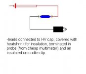
I have find the following simple tool useful to diagnose many tube amp problems. You can use it to short out preamp tube grids, to diagnose how far down the signal chain a particular noise is originating. (make a list with pen and paper) Then you have less circuit to investigate. If shorting out the early preamp grids does nothing then it is probably a ground issue.
Teemuk is right on the money about the grounding stuff. Make sure you change that cable!! (unless you want to look like this )
)
All of these amps are high gain (esp the overdrive channel) so they are going to amplify any hum at all that appears near the input side. So even if the circuit is well laid out and correct, you probably might need to take extreme measures to tame it to acceptable levels. I find most guitar amps (even the high end ones) to be rather noisy when compared to other tube gear. How does the noise level compare to other amps?
I have find the following simple tool useful to diagnose many tube amp problems. You can use it to short out preamp tube grids, to diagnose how far down the signal chain a particular noise is originating. (make a list with pen and paper) Then you have less circuit to investigate. If shorting out the early preamp grids does nothing then it is probably a ground issue.
Teemuk is right on the money about the grounding stuff. Make sure you change that cable!! (unless you want to look like this
) 
I'm with Poobah..
Turning the power switch off,the hum remains for 6-7 seconds..
So,it's not filtering,or power supply related.
The only source of AC left is the power cord,and wiring to the switch,etc. (I suppose maybe excess 'leakage' in the power x-fmr windings could cause it also?)
Pullling the plug,the hum is gone.. -good clue!
The AC cord (and associated wiring) is no longer 'live'.
I'm suspecting maybe you have the wiring for the AC power switch running past the preamp stages or something?
Try twisting the wires together,if they aren't already,and re-routing them away from the sensitive(preamp) areas of the amp.
Tucking the wires down into the corners of the chassis can help a bit also. Perhaps even try shielding them.
Actually,
PSU noise will go away when you pull the plug... rectification and recharge ripple go away at that point. But that test DOES indicate that the HUM source is not from external influences (other than the AC itself) but rather an internal problem.
We can just divide and conquer. A three wire cord won't help directly, but is a good place to start.
.
The clean channel is noisier than the clean channel of a SS Fender M80 amp that I have. The overdrive channel however is quieter than the overdrive channel of the M80 (maybe because of the harshness and noise associated with transistor or diode clipping).
Both channels are noisier than the respective channels of a friend’s SS Peavey Transtube amp which has a sort of “noise gate” implemented with two 1N4148 diodes (paralleled and opposite) in the signal path. I may try this too, but for it to work the noise level should be below 0.7 mA I think.
Both channels of the amp are noisier than respective channels of a Peavey Classic 30 tube combo, which I tried in a local shop. The Peavey’s noise also sounded a bit “brighter” than my amp’s. This however may be due to differences in design as well as the fact that my preamp tubes are NOS RFT ECC83’s which are supposedly known for their ballsy, low-endish sound.
Well, after carefully rethinking and considering all your help and replies, this is what I plan to do next:
1. Replace the power cord with a three-wire one. I’ll also temporarily dismount the fuse and power-on switches from the chassis to see if keeping them away from the power amp tube sockets has any effect. If it does, then I’ll have to place them more to the left side of the chassis – farther from the power tubes.
2. Keep the tube heating supply 6.3V/AC (as it was), but rewire it to make sure all wires are tightly twisted and elevated well above the tube sockets.
3. Try to come up with a thick cover for the PT, one side of which is sticking out inside the chassis..
4. Find/buy and install a choke for the B+ for the tubes
5. Find some preamp tube shields that fit or buy new tube sockets with shields
6. Modify the preamp layout so as to keep power grounds away from signal grounds. All PS filter caps will go to the so called “doghouse” enclosure located on top of the chassis which has enough space left to fit all caps. Each separate B+ wire going to a particular preamp tube plate resistor will be shielded, and I plan to avoid running those close to signal wires or AC heating wires. The only thing that bothers me here is that most star grounding gurus suggest that it’s best that the PS star ground is located near the PT (where the PT center taps are grounded and where it is right now) and preferably that PS filter caps should have vary short leads to that same star ground point. This is not feasible in my case because of the caps’ location. I will actually have to run one thick ground wire (or maybe even several, one for each cap) from the doghouse (where all caps will be) to the star ground point. I’m not sure if this wouldn’t ruin the idea of star grounding. At least the amp’s insights may look better I think.
Will make sure to report the results
How does the noise level compare to other amps?
The clean channel is noisier than the clean channel of a SS Fender M80 amp that I have. The overdrive channel however is quieter than the overdrive channel of the M80 (maybe because of the harshness and noise associated with transistor or diode clipping).
Both channels are noisier than the respective channels of a friend’s SS Peavey Transtube amp which has a sort of “noise gate” implemented with two 1N4148 diodes (paralleled and opposite) in the signal path. I may try this too, but for it to work the noise level should be below 0.7 mA I think.
Both channels of the amp are noisier than respective channels of a Peavey Classic 30 tube combo, which I tried in a local shop. The Peavey’s noise also sounded a bit “brighter” than my amp’s. This however may be due to differences in design as well as the fact that my preamp tubes are NOS RFT ECC83’s which are supposedly known for their ballsy, low-endish sound.
When the volume and master pots are all the way up, and the first preamp stage tube grid is shorted, the noise is reduced a lot, but still remains (say about 80-90% reduction). When the second stage is also shorted, the noise is reduced even further, and so on…..leading to almost completely quiet amp when all preamp stages are shorted (only some low freq hum - from power tubes I guess). So my feeling is that every stage adds its share to the overall noise level, obviously the first stage having the largest contribution because its noise is further amplified by the following stages.If shorting out the early preamp grids does nothing then it is probably a ground issue.
Well, after carefully rethinking and considering all your help and replies, this is what I plan to do next:
1. Replace the power cord with a three-wire one. I’ll also temporarily dismount the fuse and power-on switches from the chassis to see if keeping them away from the power amp tube sockets has any effect. If it does, then I’ll have to place them more to the left side of the chassis – farther from the power tubes.
2. Keep the tube heating supply 6.3V/AC (as it was), but rewire it to make sure all wires are tightly twisted and elevated well above the tube sockets.
3. Try to come up with a thick cover for the PT, one side of which is sticking out inside the chassis..
4. Find/buy and install a choke for the B+ for the tubes
5. Find some preamp tube shields that fit or buy new tube sockets with shields
6. Modify the preamp layout so as to keep power grounds away from signal grounds. All PS filter caps will go to the so called “doghouse” enclosure located on top of the chassis which has enough space left to fit all caps. Each separate B+ wire going to a particular preamp tube plate resistor will be shielded, and I plan to avoid running those close to signal wires or AC heating wires. The only thing that bothers me here is that most star grounding gurus suggest that it’s best that the PS star ground is located near the PT (where the PT center taps are grounded and where it is right now) and preferably that PS filter caps should have vary short leads to that same star ground point. This is not feasible in my case because of the caps’ location. I will actually have to run one thick ground wire (or maybe even several, one for each cap) from the doghouse (where all caps will be) to the star ground point. I’m not sure if this wouldn’t ruin the idea of star grounding. At least the amp’s insights may look better I think.
Will make sure to report the results
SemperFi,Dude! -50 is not positive voltage, thats negative! The heater bias MUSTbe positive.
I think I misunderstood your reply earlier and responded incorrectly (I received a lot of info and it's a bit hard for me to assimilate it all at once) - sorry.
Anyway, I currently have bias for the EL34 tubes only, and it measures -50VDC (comes from a separate PT winding).
The heater supply was and is not biased. The heater winding has a center tap which is connected to ground. I did try to bias the heating by connecting the CT to +50VDC off a voltage divider from the B+. It made no differance so I left it as it was. I might try it again, especially considering that I decided to stick with AC heating and not try regulated DC.
Thanks
yeah, actually reading your last post kinda tells me its not related to heater leakage.
This type of problem can be a real b****, and often when fixed its hard to tell what fixed it...
The fact that the noise goes down a lot when grounding the grids of the preamp tubes should give us some hints. The total gain in such an amp is huge, and any noise at the front stage will get amplified by that hugeness.
Twist the heater wiring and make sure its not parallel with any signal leads or resistors.
Same for any AC wiring.
Good luck, but remember its most likely better tonal wise to have hum than to kill the tone with too much regulation.
- Status
- This old topic is closed. If you want to reopen this topic, contact a moderator using the "Report Post" button.
- Home
- Live Sound
- Instruments and Amps
- Frustration with hum and noise in guitar tube amp