Oh, now I see.sgrossklass said:Uh... What makes you think that?
I am pretty sure that they were shooting for an input sensitivity of +4 dBu (1.23 V) balanced and -10 dBV (300 mV) unbalanced.
You are correct, I did not look at that this way.
Not yet.sgrossklass said:Have you been able to measure anything?
Might be the diode bridge after IC2B for the red clipping LED, so I just might remove R65 and test the pot for distortion.sgrossklass said:What's causing it in the first place still is totally unclear.
The VU meter is part of the noise and can be part of the distortion.
So disconnecting the AC feed to the +-17v rails and the inputs to IC5B will be beneficial.
There is also IC2A which is closed on itself and share the same ground as the main IC2B.
Maybe just disconnect pin 3 from ground and cut the trace between 1 and 2?
I have a strong feeling that this unused IC2A is the main villain whom generates the distortion.
Funky and unwanted things going inside IC2 as a whole package...
Also, running low voltage signal wires across/inside the amplifier even if they are shielded is #1 cause of interference.
So I think the pot wire and the pot itself should be removed and replaced with a simple 20k to ground at the input.
I also will remove all the wires that are going to the front panel except maybe to the Yellow Protection led which should never light and is part of the power supply and not the signal chain anyway.
There is definitely a ground problem in this amplifier because people complain about ground loops when using both the RCA jacks.
Before I begin mutilating my A500 (which will be great fun
 ), I will try the R65 and IC2 mods as it is still stock.
As soon as it arrives...
Last edited:
My A500 is here.
Right out of the box I connected as follows:
1. Used 2 pronged power cable without the ground pin.
2. RCA->TS plugs into the balanced inputs to avoid the extra gain of the RCA inputs.
3. Volume pots to max.
Results:
The input volume is controlled via a Focusrite Saffire audio interface.
Amp is quiet enough to not hear mild hiss from the twiters when my ear is a foot from the speaker, so no excess noise from the preamp stage as I expected,
although the hiss is completely gone if the pot is turned to zero.
The hiss is definitely not louder than my Aliexpress Class-D TK2050 amp hiss, or the hiss from the ribbon tweeters of my active monitors, or my PC fans.
The toroidal transformer is very quiet and no humming or buzzing is heard.
In fact, my near field active monitor toroidal transformers are noisier than the A500 if listened from same distance.
Actually, I don't feel the need to modify anything right now.
Maybe in the future if I'll want the hiss to be even quieter I'll bypass the preamp completely, but not yet.
I'm sure I'll post here again.
Cheers
Right out of the box I connected as follows:
1. Used 2 pronged power cable without the ground pin.
2. RCA->TS plugs into the balanced inputs to avoid the extra gain of the RCA inputs.
3. Volume pots to max.
Results:
The input volume is controlled via a Focusrite Saffire audio interface.
Amp is quiet enough to not hear mild hiss from the twiters when my ear is a foot from the speaker, so no excess noise from the preamp stage as I expected,
although the hiss is completely gone if the pot is turned to zero.
The hiss is definitely not louder than my Aliexpress Class-D TK2050 amp hiss, or the hiss from the ribbon tweeters of my active monitors, or my PC fans
.The toroidal transformer is very quiet and no humming or buzzing is heard.
In fact, my near field active monitor toroidal transformers are noisier than the A500 if listened from same distance.
Actually, I don't feel the need to modify anything right now.
Maybe in the future if I'll want the hiss to be even quieter I'll bypass the preamp completely, but not yet.
I'm sure I'll post here again.
Cheers
DANGER!!!
If you run this amp ungrounded the voltage potential between wall socket ground and the A500 metal chassis is over 100VAC !!
I repeat: There is a 100VAC potential on the A500 Chassis when it is un-grounded!
Don't touch anything metal in the room while working with the A500 un-grounded.
*Note my amp is 230v European version.
I take my last post back, I can't delete it, the forum wont let me.
There are some major ground issues with this amp.
Running the amp grounded, the noise got bigger.
Running the amp Un-grounded means I run 100vac back through the flimsy RCA shield to my audio interface.
Dirty dids done dirt cheap.
I will experiment and report later.
Last edited:
First, why can't I edit my previous posts?
OK, I have managed to make the amp completely silent, without hiss, hum or crackles, ALL STOCK.
1. Disconnect any UPS (uninterruptible power supply) or SCR devices in the room, this was the cause of hiss and crackling I heard.
My audio interface connected to the PC via Firewire and the PC was plugged though a UPS.
2. Use RCS to TS plug and connect into the 1/4" Balanced inputs to eliminate the extra gain boost and elevated noise floor with it.
3. Elevate the ground pin from the power cord AT YOUR OWN RISK!
Be sure you plug the inputs to give the amp ground from external already grounded source BEFORE you turn on the amp.
This will eliminate the slight hum that is left.
Now the amp is dead silent with the pots at max and delivers all the wattage I'll ever need in the house or studio.
Maybe now it deserves its "Reference" title but after some non conventional and dangerous trickery.
Still, the distortion problem is unsolved because of bad designrolleyes so the attenuation is done before the inputs via whatever you have,
but at least I don't have to drill another RCA jack to bypass the noisy preamp stage which was resolved as mentioned above.
This amp is VERY sensitive to "unclean" ground or difference in ground potentials especially at the inputs!
( Maybe because of its floating power supply topology?)
So make sure it is grounded at one point; most often than not your signal plugs are already grounded.
OK, I have managed to make the amp completely silent, without hiss, hum or crackles, ALL STOCK.
1. Disconnect any UPS (uninterruptible power supply) or SCR devices in the room, this was the cause of hiss and crackling I heard.
My audio interface connected to the PC via Firewire and the PC was plugged though a UPS.
2. Use RCS to TS plug and connect into the 1/4" Balanced inputs to eliminate the extra gain boost and elevated noise floor with it.
3. Elevate the ground pin from the power cord AT YOUR OWN RISK!
Be sure you plug the inputs to give the amp ground from external already grounded source BEFORE you turn on the amp.
This will eliminate the slight hum that is left.
Now the amp is dead silent with the pots at max and delivers all the wattage I'll ever need in the house or studio.
Maybe now it deserves its "Reference" title but after some non conventional and dangerous trickery.
Still, the distortion problem is unsolved because of bad design
rolleyes so the attenuation is done before the inputs via whatever you have,but at least I don't have to drill another RCA jack to bypass the noisy preamp stage which was resolved as mentioned above.
This amp is VERY sensitive to "unclean" ground or difference in ground potentials especially at the inputs!
( Maybe because of its floating power supply topology?
)So make sure it is grounded at one point; most often than not your signal plugs are already grounded.
Last edited:
Though it'll be a Penta post, I shamelessly will.
Built a Hum-X box with two diodes back-to-back, a 10ohm resistor and 0.1uF cap all in parallel and in series with the ground of the power cord.
Earthing (Grounding) Your Hi-Fi - Tricks and Techniques
Also I bought an RCA Ground Loop Isolator to make sure the only ground to the A500 is through this Hum-X box as it should.
Now the A500 is Quiet and SAFE!
Post #202 is relevant again.
Last edited:
Behringer A500 channel 1 broken
Hi guys,
Recently my mate used my A500 and now its broken. I guess because of aa to high input level. Only 1 channel is giving audio output and the yellow 'prot' light of channel 2 constantly burns.
Is there a common component to fail in the A500 which I can try replacing?
Would really like your help.
Here's an Image of the module:
Here a video of what the amp does when I twist the pot of the channel:
https://youtu.be/RajonKwVsOs
greets
Hi guys,
Recently my mate used my A500 and now its broken
. I guess because of aa to high input level. Only 1 channel is giving audio output and the yellow 'prot' light of channel 2 constantly burns. Is there a common component to fail in the A500 which I can try replacing?
Would really like your help.
Here's an Image of the module:
An externally hosted image should be here but it was not working when we last tested it.
Here a video of what the amp does when I twist the pot of the channel:
https://youtu.be/RajonKwVsOs
greets
... Running the amp grounded, the noise got bigger ....
Hi !
are you driving the amp through the balanced inputs ?
Thanks, gino
Last edited:
The yellow 'prot' light of channel 2 constantly burns.
Is there a common component to fail in the A500 which I can try replacing?
According to the schematic the Yellow "PROT" led is there to show failure in the +15 and -15 voltages.
You would have to measure the outputs of D29 and D30 zener diodes which create these voltages.
If IC4 or IC3 are dead and shorting the +15V an -15V somehow, the yellow led will glow.
Do the measuring with amp turned on and properly grounded.
IMORTANT NOTE: The ground of the PCB goes through the screws of the heatsink, so you would have to ground the heatsink manually before plugging in the power.
Measure D29 and D30, you should read -15 and +15.
Measure pins 8 and 4 of the 4580 IC3 and IC4 you should also read -15 and +15.
In reference to ground of course.
A more simple method would be to measure on D24 and D25 as they a directly connected to the +15 and -15 rails.
* Can you please take a photo of the PCB again but upside down (not face down) so I can see behind the big black caps.
Also face down if you can.
I have read in other thread about this problem, they replaced the input IC4 and all was back to OK.
Lets try to solve this.
My analysis of the Power Supply and the Yellow PROT Led.
R60 is PTC Thermistor which sits on top of one of the 4 big power transistors is 70ohm (measured on my real amp) at room temperature.
When the power transistors heat up to about 100-120 deg (C), a typical PTC raises to about 3-4k ohm.
In normal operation temperature:
T1 (PNP) base is held above -700mV (base to emitter) so it is open and no current flows through it.
Thus not sending current to T3 (NPN) which is held below 700mV through R47.
This will also hold T2 (PNP) base at below -700mV through R45 so T2 is close and the current flow through it and not through the Yellow PROT Led.
In abnormal high temperature:
The PTC goes above 3.7k (+-) thus taking T1 base below -700mV and allows current to flow to T3 and closing it thus shorting +15V and -15V (zener generated) and muting the amp.
This also takes T2 base above -800mV and opens it, thus the current flows through the Yellow "PROT" Led and lights it.
When +15V and -15V shorted through T3, T3 gets hot and also R2 and R4 (1.3k) which limit the current to the +-15V rails and through T3.
I read somewhere on diyaudio that someone bought a A500 second hand with the 1.3k 5W resistor charred/blown.
I verified this by opening my amp top case and running it with no input signal.
T3, R2 and R4 are hot to touch at room temp but I still can hold my finger on them.
If R60 PTC thermistor triggers T3 to close this can overheat the 5W R2/R4 resistors.
When the yellow light turns on ==> Turn Off your A500 as suggested by the manual.
Sometimes if the opamp fails it can short the +15 rails and the yellow light will turn on without temperature overload.
Disclaimer: I am no expert, I just deduct from what I measure and I might be (very) wrong.
An externally hosted image should be here but it was not working when we last tested it.
R60 is PTC Thermistor which sits on top of one of the 4 big power transistors is 70ohm (measured on my real amp) at room temperature.
When the power transistors heat up to about 100-120 deg (C), a typical PTC raises to about 3-4k ohm.
In normal operation temperature:
T1 (PNP) base is held above -700mV (base to emitter) so it is open and no current flows through it.
Thus not sending current to T3 (NPN) which is held below 700mV through R47.
This will also hold T2 (PNP) base at below -700mV through R45 so T2 is close and the current flow through it and not through the Yellow PROT Led.
In abnormal high temperature:
The PTC goes above 3.7k (+-) thus taking T1 base below -700mV and allows current to flow to T3 and closing it thus shorting +15V and -15V (zener generated) and muting the amp.
This also takes T2 base above -800mV and opens it, thus the current flows through the Yellow "PROT" Led and lights it.
When +15V and -15V shorted through T3, T3 gets hot and also R2 and R4 (1.3k) which limit the current to the +-15V rails and through T3.
I read somewhere on diyaudio that someone bought a A500 second hand with the 1.3k 5W resistor charred/blown.
I verified this by opening my amp top case and running it with no input signal.
T3, R2 and R4 are hot to touch at room temp but I still can hold my finger on them.
If R60 PTC thermistor triggers T3 to close this can overheat the 5W R2/R4 resistors.
When the yellow light turns on ==> Turn Off your A500 as suggested by the manual.
Sometimes if the opamp fails it can short the +15 rails and the yellow light will turn on without temperature overload.
Disclaimer: I am no expert, I just deduct from what I measure and I might be (very) wrong.
Attachments
I installed a proper soft start which I bought from Ebay:
Amplifier Board Sound Power Start Protection High Power Soft Start Board | eBay
It work good and does the job very well.
It looks exactly the same (schematic-wise) as the one from diyaudio store but Chinese.
Like this: http://www.google.com/url?sa=t&rct=...PxNLwy6JC0iuCl0sc5oBWrg&bvm=bv.93564037,d.d24
Now what's left is to bypass the pots with a simple 20k resistor and a JST 2.0mm PH 3-Pin Connector.
I wanted to keep the pot cable stock in case I'll need to sell the amp, so I bough a connector just like it.
Sorry for the blurry images.
An externally hosted image should be here but it was not working when we last tested it.
An externally hosted image should be here but it was not working when we last tested it.
Last edited:
Hi All
new here so please be gentle !
I've been running 2 x A500's for a couple of years now
Active x-over (80Hz)
one running a pair of sound craft studio monitors, the other bridged running an 8ohm Sub.
I was running some LF tests yesterday (20-50Hz), at about 90% max power on the sub amp - at no stage did the front panel clip led light.
after a few mins of this test, the sub stops working.
My first thought was that the Sub speaker had given out.
immediately powered everything off, disconnected and checked the system bit by bit.
Turns out that one of the channels (channel B) on the A500 in bridge mode has died - no output at all - the other channel is still working fine.
I've popped the cover and initial observation is that the amp pcb LED on the amp that is non functional is not lit - ref des is LD2.
Cant find any reference in the manual to the purpose of this LED - any clues please?!
Looking to delve in deeper today with a view to fixing it - can't imagine it being too difficult - I have got around 20 years of electronic design experience behind me.. and a fair bit of test kit.
The amp design itself looks pretty conventional (from a PA POV)
However, any early heads up, gotchas etc would be much appreciated.
thanks in advance
David
holy thread resurrection !
After having some free time to look at the amp on the bench, I've found that a 15V Zener is SC.
(it's the one that provides the +15v for the op amp supply - D29)
The fact that R34 was trying to burn itself off of the PCB gave me a clue.
LD2 does come on for around half a second at power up;
BUT, and heres the strange thing - there is no -VCC rail;
Bridge diodes buzz out OK.
So, I think that there is another issue somewhere; but I'll replace the Zener first and go from there.
I've checked (power off) the -VCC rail for shorts, but non found.
ah well !
keeps me out of trouble
morning.
thought I'd update the thread with my findings.
Amp all fixed - it was just the Zener diode !
shocked that the diode was the only thing dead
19p from Maplin (quickest route to get one !)
all fixed & working well.
In fact rather too well... full power testing into my dummy load... it blew one of the power resistors up - proper good bang, smoke everywhere, end cap flew off it
ah well, obviously need to build a bigger one now !
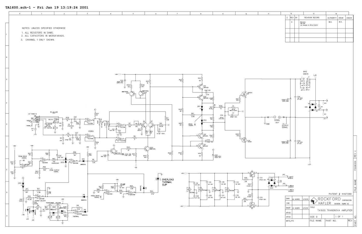
Hi everyone, I just found (and wanna share) the Hafler TA1600 schematic that - according to many pro-listeners - sounds very very very well:

I'm non into electronics/circuitry design, but hope this can help the project.
Thank you!
Someone - on another HiFi forum - shared this page that contain the OFFICIAL A500 schematic (note: wait a minute or so to obtain the PDF download button, it will appear on the right of "This file is downloadable free of charge"):
BEHRINGER A500 VER.G SCH
Hope that helps.
BEHRINGER A500 VER.G SCH
Hope that helps.
For those who own the A500 amp, I've added the - incomplete - entry @ gearogs:
Behringer - A500 | Gearogs Database & Marketplace
Behringer - A500 | Gearogs Database & Marketplace
Hi sorry for this late question but i still have this amp ... if i understand well the RCA input goes directly to the amp board while the XLR input passes to a summing op-amp ?
Would it be better than to use the unbalanced inputs and so bypassing an opamp ?
unfortunately i cannot get the schematic
And more a general question ... are all the xlr inputs done this way ? because internally all amps look unbalanced to me
Would it be better than to use the unbalanced inputs and so bypassing an opamp ?
unfortunately i cannot get the schematic
And more a general question ... are all the xlr inputs done this way ? because internally all amps look unbalanced to me
- Status
- This old topic is closed. If you want to reopen this topic, contact a moderator using the "Report Post" button.
- Home
- Live Sound
- Instruments and Amps
- Behringer A500 as a DIY project