ok, let me come to spam your thread")
Haven't been at diy audio for quite a while but glad i found this. It looks perfect for my purposes, i'm planning Kreutzers preamp for quite long but never got to make it. I tried a regular baxandall integrated in the bass but it just lost too much from the signal.
So i guess i'll be building this one soon too probably with the 3-band EQ but it still depends whether i put the gain switch or something as i have only place for 4 knobs. I could use push-pull knobs though if the place gets too small.
One thing i was wondering, would a balance pot between my two P/U's make i good difference or do u guys think its unnecessary?
The bat holder is another subject i must think of also, maybe i could fit it inside the electronic 'cavity' but opening and closing could become a bummer...i could add a recharging circuit though, with the DC jack on the back of the bass i think my website is supposed to be on the sig so there's some pics of my cheapo bass and the baxandall (i think it was baxandall, cant really remember) anyway...it didn't work out well
Haven't been at diy audio for quite a while but glad i found this. It looks perfect for my purposes, i'm planning Kreutzers preamp for quite long but never got to make it. I tried a regular baxandall integrated in the bass but it just lost too much from the signal.
So i guess i'll be building this one soon too
probably with the 3-band EQ but it still depends whether i put the gain switch or something as i have only place for 4 knobs. I could use push-pull knobs though if the place gets too small. One thing i was wondering, would a balance pot between my two P/U's make i good difference or do u guys think its unnecessary?
The bat holder is another subject i must think of also, maybe i could fit it inside the electronic 'cavity' but opening and closing could become a bummer...i could add a recharging circuit though, with the DC jack on the back of the bass
i think my website is supposed to be on the sig so there's some pics of my cheapo bass and the baxandall (i think it was baxandall, cant really remember) anyway...it didn't work out wellThey now make batt holders for guitars to allow easy access. It might be worth the effort.
I put my batt behind the pick guard along with the electronics. It's not very handy for changing, but I only have to do it every 10 - 12 months, even with a lot of use. I check the batt when changing strings.
A balance pot would be hard to do since you want both pickups at full volume with the pot in the mid position. Two volume pots or switches would be easier.
Yes you're right on that, i currently have two volume pots, but i guess the circuit had to do somhow changed for that? Anywa, i lack of space for pots and i want the 3-band Eq so the only way would be to use p-p pots which are again larger. so i'll just forget this now, although i've wired the bass for 2 separate volumes, i'm actually only using them at the max anyway.
I guess i'll also forget the recharger circuit and if the battery really lasts that well, it won't be a problem as my electronics are on the back of the bass with a cover which opens with 2 screws. not like in strato's under the strings.
I guess i'll have some build pics after its finished, after few days, weeks, or months
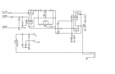
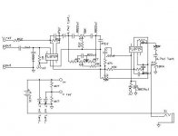
DolbyR said:Just one question..at first i thought its just a regular voltage divider in the circuit, by now that i start looking better at it, it doesnt exactly look like it...where does the the battery's [-] pole connect? just through a switching jack to ground?
Yes, through the jack to ground, so it switches the power ON when you put a plug in, it's standard practice.
You are also correct in your thought that it uses a simple voltage divider to give a split supply, the two 4k7's.
DolbyR said:thanks for the quick answer..
i'm still not advanced in reading schematics, but from what i understood, only half of each of the 4 opamps in the 3-band version is used...am i correct? a TL071 would work as good then too?
It would, but the original circuit only used TWO eight pin chips, each with two opamps in! - this is done to save space.
Job Done....
Hi All
I have built the three band version, with boost switch. Brion55 is absolutely right; you do NOT want to switch the feedback resistor. You can, but the resulting bang could cause serious damage to amp and hearing. Fortunately, I tested on very low volumes (always wise, I find) and before I could even post a question about it, Brion55 had posted the answer.
I squeezed the whole thing onto a bit of veroboard 25x17 (because of space restrictions in the guitar) so there are some pretty major contortions, but it all works pretty well.
The boost equation provided a little more than I wanted, so I changed RG2b from 2.4k to 5.1k which tames it a bit (from vg=4 to vg=2ish). But now I think it may need just a tad more, so I will go with a 4.7k in future versions.
Boost switch is via a push/pull DPDT switch on the volume pot, and is smooth as you like (no amp breaking thumps)
I also could not find a .0039mf cap, so I used a couple in series to get to the same value. Works fine.
There were some serious issues with buzzing if everything was turned up full, but these seemed to resolve themselves before I even got round to troubleshooting the earthing issues which seemed to be causing them. It is now a quiet circuit with a wide range of tones available. Thanks to everyone for all the help and advice.
Cheers.
Attachments
Could somebody check this schem, if it looks correct? ive already almost finished the preamp according to it...it should actually be same as brions original "big brother". Just what i'm wondering is, i suppose v+ and vref should also be connected to the opamps, on the chem nothing is now connected to v+/v-...should it be connected to both opamps or only the first?
Attachments
New viewer: This all looks very good, I'm thinking about the same thing at present:
a thought: instead of the midrange eq in the 3-band, how about a notch filter switch? (ie just preset with the right freq,bandwidth and gain) . Reason I ask is because i have a gallien kreuger bass head which has a notch filter which is ESSENTIAL to get the sound i like on my pbass special (1 p, 1 j pickup) and i'm thinking of building a preamp with the same filter settings along with usual bass and treble pots.
Also would have jfet input buffers and pan-pot type blend control (wouldn;t matter about 3db loss in middle of pot if pickups are buffered).
Anyway great thread, go for it , I'm happy to see so much discussion.
Re: Job Done....
Hi DolbyR according to Scummer's mod you must feed the opamp with +9v (pin 8) and -9v (pin 4), you are probably connecting +9v (pin 8) and common ground (pin 4). I simulated it in Multisim 9 that way and heard no sound. If you have Multisim 9 you can record a 10 sec. sound sample (from your guitar or bass) simulate it and then hear it to see if it actually works, before breadboarding. This tone control circuit is great. Best Regards.
Scummer said:Hi All
I have built the three band version, with boost switch. Brion55 is absolutely right; you do NOT want to switch the feedback resistor. You can, but the resulting bang could cause serious damage to amp and hearing. Fortunately, I tested on very low volumes (always wise, I find) and before I could even post a question about it, Brion55 had posted the answer.
I squeezed the whole thing onto a bit of veroboard 25x17 (because of space restrictions in the guitar) so there are some pretty major contortions, but it all works pretty well.
The boost equation provided a little more than I wanted, so I changed RG2b from 2.4k to 5.1k which tames it a bit (from vg=4 to vg=2ish). But now I think it may need just a tad more, so I will go with a 4.7k in future versions.
Boost switch is via a push/pull DPDT switch on the volume pot, and is smooth as you like (no amp breaking thumps)
I also could not find a .0039mf cap, so I used a couple in series to get to the same value. Works fine.
There were some serious issues with buzzing if everything was turned up full, but these seemed to resolve themselves before I even got round to troubleshooting the earthing issues which seemed to be causing them. It is now a quiet circuit with a wide range of tones available. Thanks to everyone for all the help and advice.
Cheers.
DolbyR said:Finally get to test te preamp, but no sound whatsoever so i guess i´ll just "freeze" this project for now. its built on protoboard so even troubleshooting will b too difficult.
Hi DolbyR according to Scummer's mod you must feed the opamp with +9v (pin 8) and -9v (pin 4), you are probably connecting +9v (pin 8) and common ground (pin 4). I simulated it in Multisim 9 that way and heard no sound. If you have Multisim 9 you can record a 10 sec. sound sample (from your guitar or bass) simulate it and then hear it to see if it actually works, before breadboarding. This tone control circuit is great. Best Regards.
Have a look at this Tl082 opamp diagram, I think it is very clear to understand, if the 3 band tone control circuit has 4 opamp symbols, you will use just 2 dual opamps like the Tl082 or the Tl072, for this opamp (and most duals) pin 4 is V- and pin 8 is V+, if you are going to feed both opamps with 9v you will have to use 2 9v batteries, connecting the "A" 9v battery positive terminal to "B" 9v battery negative terminal and this node to Common Ground, then feed the opamps connecting "A" battery negative terminal to V- and "B" battery positive terminal to V+.
I simulated the same circuit using 2 Tl072 dual opamps and with 2 Tl082's, I used a cheap Yamaha 4 string bass, and the preamp gave it a full bodied sound with lots of presence.
I simulated the same circuit using 2 Tl072 dual opamps and with 2 Tl082's, I used a cheap Yamaha 4 string bass, and the preamp gave it a full bodied sound with lots of presence.
Attachments
Preamp circuit upgrade
DolbyR, (sorry I misunderstood your explanation!) I have tested the circuit with just one 9v battery, as you know feeding opamps this way works (connecting +9v to pin 8 and common ground to pin 4), probably you damaged the opamps when you tried to figure out how to connect the supply voltage.
I also thought about a way to minimize hum, replace the Vref circuit for a single TLE2426 IC (The Rail Splitter Precision Virtual Ground) it not only saves space! (1 tiny 3 pin IC in place of 2 electrolytic caps and 2 resistors) this IC's output voltage is always equal to one half the supply voltage!
Also remember the star grounding method to minimize hum, I think you get more presence with TL082's, but its just a matter of taste. Regards.
Attachments
- Status
- This old topic is closed. If you want to reopen this topic, contact a moderator using the "Report Post" button.
- Home
- Live Sound
- Instruments and Amps
- 2-band bass guitar onboard preamp