Hello.
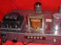
I recently acquired a 1965? BOGEN M330A tube PA amplifier during clean-out of a storage room at work. It’s in perfect perfect condition. I don't think it was ever even plugged in. The AC cord was still rolled up with a string tied around it and an inspection tag attached to it. If it will help, I can list all the features, inputs, outputs, controls, etc. I can also send photos. For tubes, it has 2x 7868s, 2x 6EU7s and 1x 7247. I did a controlled power-up through a variac and everything seemed fine. Then I brought it to Urban Antique Radio in CT for an assessment. Mike checked it out and we plugged a CD player into it and it sounded great!
Since I can't afford a "real" tube guitar amplifier, I was hoping to use the Bogen. I can play my guitar through one of the MAG-TAPE inputs and it sounds so beautiful (the amp, not my playing). I found the following sites (a few years old) and they sound like exactly what I want to do but I’m a mechanical engineer, not electrical, so there is not enough detail for me to actually do anything. Also, I know these things can kill you so I don’t want to fool around with it before I learn what to do.
“Converting Integrated/PA Tube Amps into Guitar Amps” by Joe Jasniewski
http://www.rru.com/~meo/Guitar/Amps/PA2Guitar/index.html
(Jasniewski@elesys.eng.pko.dec.com)
“Notes on Converting PA Amps to Guitar Amps” author unknown
http://www.rru.com/~meo/Guitar/Amps/PA2Guitar/pa2g-notes.html
THE POINT: If I supply the schematic and manual, will someone please give me specific instructions for how to re-wire it to achieve what is described in Mr. Jasniewski’s paper? I’m handy with a soldering iron and meter and I’m respectful of the potential hazards (no pun intended) so I’m sure I can do the work if someone will tell me what to do.
Thanks.
Zeke,
If you post the schematic, I'm sure we could come up with something.
You could first try tweaking the tone stack, as mentioned in the articles. If you go with the Baxandall / James tone controls, try the James circuit in Duncans Tone stack calculator.
If this gets you the sound you want, great, you are done.
I tried this on my first pa amp conversion about 10 years ago. I was hoping to use the stock circuitry as much as possible. While the clean sound was pretty good, the overdriven sound was a bit harsh, and it just didn't respond the way it should. I eventually tore out all the ciruitry and went with the tried and true Fender AB763 topology, and never looked back. The Pa amp sounded like a really good Fender. I have done 4 pa amp conversions over the years and have used both the 5F6A and AB763 topologies with success. The best sounding one has a modified 3 stage AB763 preamp into a 5F6A power amp, with presence control and post phase inverter master volume.
I am not familiar with the 7868s, and 7247. The 6EU7s are similar to 12AX7s and they are easily available, not too expensive. Don't know about the other tubes. I personally would use readily available tubes like 6L6 and 12AX7.
-
Mike Donovan
Thanks for your response.
I'll try to post the manual, including the schematic, (zipped pdf) separately for use in this discussion. I don’t know what disclaimers are necessary but I bought it from MusicParts.com. Hopefully the manual will go through. If not, I can post the schematic I did in AutoCAD.
I appreciate your comments about the overdriven sound. This is exactly right for blues. As is, it sounds wonderfully clean and creamy from strong full bass to shimmering highs but I’d like the option to dirty it up.
I’m anxious for your (and anyone else’s) comments on what I might do with this great old amp.
I guess the manual is too large. Here's a zipped Word file into which I'd pasted the AutoCAD drawing. (is there a simpler way?) It's missing the main power section because I haven't CADed it yet. If you need it, let me know.
Thanks for your seggestions.
Thanks for your seggestions.
Attachments
Zeke,
Got the schematic. There are several issues with this circuit for guitar uses
Preamp V1A, V1B, V2A
6EU7s configured with "grid leak" biasing method, not a bad idea for its intended use, but not so good for a guitar amp. Fender did this in very early amps and quickly switched to the standard cathode bias scheme. You probably don't need 3 inputs either.
The next problem is the "mixing bus". The signal goes thru one volume control directly into another one. This is lame for guitar. That master volume needs to be later in the chain.
Next comes the tone stack. It's probably all wrong for guitar. You could redo the existing tone stack or put in a Fender/Marshall/Vox tone stack. Since you already have two 1 Meg pots, a Vox style tone control would work.
Now we get to the power amp section. This is a pretty standard output stage for a PA amp, but not optimal for guitar. Most likely there is too much Negative feedback. I'm not too crazy about those 15k plate resistors on the output tubes either. That's pretty bizarre, as are the output tubes themselves.
Overall, the circuit could be greatly improved for guitar amp purposes, but would require major rewiring. You could maybe get by with tweaking the tone controls, moving the master volume, and lowering the Negative FeedBack.
To me, though, this amp is a good candidate for 5F6A bassman / Marshall Plexi conversion.
-Mike Donovan
Mike,
Thanks. my naivete is showing.
Is it too much to ask you (or anyone else) to edit the schematic to show me exactly what to do? What to re-wire?, what parts to replace with what values?, etc. I can email the AutoCAD drawing if it would help.
I’m willing to research the topic and do the work myself, I’m not afraid of major re-wiring, but I just don’t have the electronics knowledge to translate the information and diagrams specifically for use with my schematic, and make the best use of the existing parts.
For example, what’s negative feedback? (I assume we’re not talking ebay")
Thanks for your patience.
Thanks. my naivete is showing.
Is it too much to ask you (or anyone else) to edit the schematic to show me exactly what to do? What to re-wire?, what parts to replace with what values?, etc. I can email the AutoCAD drawing if it would help.
I’m willing to research the topic and do the work myself, I’m not afraid of major re-wiring, but I just don’t have the electronics knowledge to translate the information and diagrams specifically for use with my schematic, and make the best use of the existing parts.
For example, what’s negative feedback? (I assume we’re not talking ebay
Thanks for your patience.
Zeke,
Negative Feedback is where a portion of the output signal is "fed back" to an earlier gain stage in the amplifer. It is ideally 180 degrees out of phase with the input signal and it does the following things:
- Makes the gain more predictable because it is relying on passive components to set the gain. Without NFB, the gain can vary as the tubes age or the line voltage fluctuates.
- Reduces harmonic distortion
- smooths out the frequency response
- Decreases the output impedence and improves damping factor.
In the Bogen, the NFB resistor is R42 which feeds some of the output signal back to the cathode of V3A. The gain of the power amp (everything to the right of the tone controls) is determined by the ratio of R42 to R34. By the way, R34 is indicated as 180k, this is really high for this resistor. I believe it should be more like 180 ohms. The more gain stages involved in the feedback loop, the greater the risk of instabilty (the amplifier becomes an oscillator).
You then need compensation capacitors to diddle with the frequency response and the phase response. In the Bogen this would be C25, which bleeds some high frequencies to ground. It was common for tube hi-fi and PA amps to use 20 - 30 db of feedback. In other words the voltage gain with feedback would be 1/10th to 1/30th the gain without feedback. Guitar amps typically use 6 - 15 db feedback (1/2 to 1/5 the open loop voltage gain) and a shorter feedback path. This provides a subjectively smoother overdrive tone. Some guitar amps dispense with NFB altogether. It's all a matter of personal preference but I generally prefer an NFB loop with a presense control.
On your amp, start by increasing R42 to 47k. The will decrease the ampunt of Negative Feedback. For now, leave the rest of the power amp section alone (everthing to the right of the tone controls)
Next, download the Fender Bassman 5F6-A schematic http://www1.korksoft.com/~schem/fenderamps/bassman_5f6a_schem.pdf
Look at the 12AY7 on the Bassman. Wire up your V1A and B like the 12AY7. Get rid of all the funky input capacitors and other tone-sucking components in the signal path. If the bassman doesn't have it, you don't need it.
Wire up your V2A and B like the first 12AX7 in the bassman.
For the tone controls, if you want to keep the existing 1 Meg pots, try the Vox AC-30 tone control.
http://www1.korksoft.com/~schem/voxamps/topboost_preamp.pdf
otherwise copy the bassman tone controls. If you can't accomodate a midrange control, you can replace the 25k pot with a 10k resistor.
Put the master volume control right after the tone controls. The wiper of the MV control goes to the grid of V3A. The "Top" of the MV pot goes to the wiper of the treble pot. The "Bottom" of the MV pot goes to ground.
You should be able to dial in clean and crunchy sounds from the preamp. Try jumping the two channels for more preamp boost. For the full-on overdriven tube amp sound, you need to push the output tubes into overdrive, by cranking up the master volume. With the preamp gain controls and the master volume, you should be able to get a good balance of preamp/poweramp overdrive characteristics.
You should also replace the power supply filter caps. The old ones tend to go bad at an unpredictable time. I like to replace all electrolytic caps and often the coupling caps to the power tube as these tend to get "leaky" and screw up the output tubes bias.
-Mike
zeke said:Mike,
Thanks. my naivete is showing.
Is it too much to ask you (or anyone else) to edit the schematic to show me exactly what to do? What to re-wire?, what parts to replace with what values?, etc. I can email the AutoCAD drawing if it would help.
I’m willing to research the topic and do the work myself, I’m not afraid of major re-wiring, but I just don’t have the electronics knowledge to translate the information and diagrams specifically for use with my schematic, and make the best use of the existing parts.
For example, what’s negative feedback? (I assume we’re not talking ebay
Thanks for your patience.
Hi,
Just answered your Email. Sorry it took so long. I have converted many a Bogen PA to guitar amp and they really rock if done right.
The first thing you could decide on is what type of preamp you wish to clone. The poweramp section is fine as is unless you want to add a presence control. Check the link I sent you by Email. Oh,
here it is for any others with interest,
http://www.geofex.com/Article_Folders/old2new.htm
A Fender type preamp is great if that is what you want, they are also easy as pie to clone. With all those extra preamp input tubes not doing anything you could build just about anything. The more complicated though the more chance of
noise and other probs surprising you.
So what is your FAV guitar amp? Some of the easy ones are,
Most Fenders
Early Marshall
Vox
Let us know how it goes
mjd_tech said:Zeke,
You should also replace the power supply filter caps. The old ones tend to go bad at an unpredictable time. I like to replace all electrolytic caps and often the coupling caps to the power tube as these tend to get "leaky" and screw up the output tubes bias.
-Mike
Good advice!!! +1
Thanks Mike and adamamp for your comments. I’m all for keeping things as simple as possible but, as Einstein said, not more so. I’m currently revising the schematic to show the planned modifications. So far, I’m thinking I’ll implement the 5F6A pre-amp design and the AC-30 tone control as Mike suggests.
A few questions:
Can you specify exactly which “input capacitors and other tone-sucking components” I can get rid of?
Can I use the component values exactly as shown in the referenced (5F6A and AC30) schematics or do I have to change their values somehow to work with my specific amp’s power, voltages, tubes, etc.? I’m concerned, for example, that the Bogen shows voltages like 455v, 440v, 350v within the circuit while the 5F6A shows 430v, 385v, etc.
By the way, I’ve revised and attached (zipped AutoCAD drawing) the as-built schematic to include the main power section. (Mike, you’re right, R34 is 180 ohms, not 180k.)
Should I implement a “standby” switch? Where should it go in the circuit?
What do you mean by “jumping the two channels for more preamp boost”?
Which ones are the power supply filter caps?
I noticed that the 5F6A has Bright and Normal channels and the only difference between them is that the Bright channel has an additional .0001 capacitor. Can I simple add a selector switch to include/exclude this capacitor on both my channels for selectable Bright/Normal tone?
Thanks.
Attachments
Zeke,
for an example.
Here, Marshall uses separate cathode resistors for the input stages and a bypass capacitor on one of the 470k mixing resistors, as well as different cathode bypass capacitors and coupling capacitors for the two channels. Some folks find the plexi "bright" channel too bright and revert to a more bassman-like configuration. It all depends on the rest of the amp, speakers, guitar and personal preference. You could put in a switch to jump the channels and avoid having so many input jacks. I use a footswitch that connects the guitar signal to the second channel for a "lead boost". The first channel is always connected.
I'm looking at the schematic you posted in Word Format, I don't have anything that reads AutoCad. The capacitors I am referring to are C1, 2, 9,10,11, 12,13 and resistors R13,14,15,16. Also the components associated with the aux input R17,18 and C14.Can you specify exactly which “input capacitors and other tone-sucking components” I can get rid of?
I wouldn't worry too much about the differences in voltages. The voltages on a Fender schematic are very much a "ballpark" figure anyway,with many schematics indicating a +/- 20% tolerance on voltage readings. The Bassman preamp will work over a fairly wide range of voltage.Can I use the component values exactly as shown in the referenced (5F6A and AC30) schematics or do I have to change their values somehow to work with my specific amp’s power, voltages, tubes, etc.? I’m concerned, for example, that the Bogen shows voltages like 455v, 440v, 350v within the circuit while the 5F6A shows 430v, 385v, etc.
The standby switch is more a convenience feature rather than an absolute necessity. I like to have one in my amps. I generally place the switch after the main filter caps as in the Fender AB763 schematics. See http://www1.korksoft.com/~schem/fenderamps/super_reverb_ab763_schem.pdfShould I implement a “standby” switch? Where should it go in the circuit?
for an example.
The bassman has 4 inputs, 2 for each channel. You plug the guitar into the bright channel, input 1, then run a patch cable from input 2 to the normal channel input 1. Then you can crank both channels gain controls to overdrive the next stage. The two channels have a slightly different frequency response and you can use this effect as a tone control. For a greater difference between the two channels, check out the Marshall Plexi http://www1.korksoft.com/~schem/marshallamps/1987_plexi.pdfWhat do you mean by “jumping the two channels for more preamp boost”?
Here, Marshall uses separate cathode resistors for the input stages and a bypass capacitor on one of the 470k mixing resistors, as well as different cathode bypass capacitors and coupling capacitors for the two channels. Some folks find the plexi "bright" channel too bright and revert to a more bassman-like configuration. It all depends on the rest of the amp, speakers, guitar and personal preference. You could put in a switch to jump the channels and avoid having so many input jacks. I use a footswitch that connects the guitar signal to the second channel for a "lead boost". The first channel is always connected.
Usually the physically largest caps in the amp. You may have a multi-section cap, which is 2 or more caps in one large can. These can be hard to find these days and when you do find them, they tend to be expensive. If space permits, I use either radial or axial caps inside the chassis. You can leave the can cap in the amp if it looks cool to you, just disconnect it.Which ones are the power supply filter caps?
Yes, you can put this cap on both channels and make it switchable, like the AB763 era Fenders.I noticed that the 5F6A has Bright and Normal channels and the only difference between them is that the Bright channel has an additional .0001 capacitor. Can I simple add a selector switch to include/exclude this capacitor on both my channels for selectable Bright/Normal tone?
Hi, I noticed this thread about converting a Bogen PA to a guitar amp, and I thought I'd ask a similar question: Can a PA amp be "converted" to be used as a "hi fi" amp? The reason I ask is because I recently aquired a pair of mono 10W Bogen Challenger PA amps. They have an RCA input labeled phono, and a screw-on type input labeled Mic. There are three pots:Volume for MIC, volume for phono, and Treble. There is a 3 pronged speaker socket on the back, as well as a standard screw terminal speaker output for 4, 6, and 8 ohm as well as one labeled 24V (?). Each amp uses two tubes, a 12AX7, and a 7868 (Sylvania). I hooked up a portable MD player and a Discman to the single RCA connecter on each amp labeled phono, and connected a pair of Paradigm Titan speakers. The amps I think sound pretty decent, but not especially sweet or special. The sound is pretty clear, maybe with a bit of low hummy buzz due to the fact that they may need new caps. If turned up much beyond the halfway mark on the volume, they distort a little, but only on loud, dense, or bassy music. The distortion is more like and overdriven sound on a guitar amp.
So I have a few questions for the people that know more about this type of thing than me:
What exactly is the difference between a PA amp and a "hi fi" amp?
I don't have a schematic for these, does anyone know where I could get one? Although they are very simple, I could probably draw my own schematic by tracing the wires.
Since the input is labeled phono, I assume this means it's for a turntable. But I plugged a Discman at full volume into it and it didn't seem to have a severely distorted effect like I would expect when you plug a line level input into a phono pre. Like I said, only slightly overdriven when at near max volume. Could amps like these have some sort of built in phono preamp? I have not tried plugging a turntable directly into it though.
I'd like to rebuild these and modify them if possible to be optimized for music listening as a mono block type set up with a preamp of some sort. Could I or should I disconnect the Mic input to improve sound or eliminate any unneeded parts? Maybe there are some resistor values to be changed or removed (or added) somewhere? Maybe with capacitors too? Of course this is assuming there is some difference in a PA amp and a hi fi amp.
Since I got these for very cheap, I don't expect to make anything super amazing out of them, but I figure there might be some things I could do to improve their sound a bit and use them as a small stereo for a small bedroom to be used at medium and low listening volumes. Even if I replaced a bunch of parts this would still cost me less than $100 for a little mono block tube stereo/bookshelf type system.
Last question: Am I crazy for thinking I could make a good sounding little mono block stereo out some junky little PA amps?
This is my first post in this forum, as I just registered, so I hope I haven't intruded on this discussion or anything. There was a lot of useful info here already on going from a PA to a guitar amp, so I thought someone might now how to go the other way. Thanks for any help anyone can give me.
Kevin
so I hope I haven't intruded on this discussion or anything.
Ban him! Nah, just kidding, but you should have started it in a new thread.

What exactly is the difference between a PA amp and a "hi fi" amp?
Often PA amps are designed fairly conservatively, so they can be left on for 20 years and not die. No kidding. But many of the best amps (example: LEAK TL12 point one) were used for PA but were also very good for hifi.
In my opinion, you would be best off stripping back all of the old components and building a "modern" design. You only need to change passive components like caps and resistors, build a much simpler design with perhaps 10 components per channel. If the amps already work, you're halfway there.
The 7868 is a bit of an oddball, but it is easy to drive. You could possibly chuck in a EL84 instead, but it has a different pinout.
If your 7868s are a bit weak, there will not be too much power. The amp should go fairly loud before distorting (depending on speakers of course.) If they seem to have a fair bit of grunt then the 7868s are probably ok.
I would adapt a SE 12AX7- EL84 schematic. There are plenty on the net. You could probably get away with 1/2 12AX7 (its a dual triode in one glass) into a 7868. Very conventional but will work just fine.
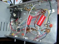
If you have a digi cam, post photos of the top and the wiring, you can attache them to your posts.
IMHO, you have a good little project there, well worth doing.
Thanks for your advice ShiFtY. It's encouraging to know that these little amps would be worth the trouble to rewire and rebuild. Since the 7876s are hard to come by it seems, and are pricey, I think the sensible thing to do, as you suggested, is to adapt a 12AX7 EL84 design to what I already have. But I don't have the experience to know what would be appropriate. I'll try attaching some pics of the bottom wiring and top layout, and if you have a suggestion or a link to a suitable design, that would be great.
I'm not a complete novice, I know how to solder and not electrocute myself inside a tube amp, but this is my first experimental rebuild, so I need help finding a design. A parts list would be a big plus as well. Again, thanks for the help on this.
Kevin
I'm not a complete novice, I know how to solder and not electrocute myself inside a tube amp, but this is my first experimental rebuild, so I need help finding a design. A parts list would be a big plus as well. Again, thanks for the help on this.
Kevin
Attachments
Bogen M330a for Guitar
Hi,
Thanks for all the suggestions.
Here’s the Bogen M330a schematic I modified to implement the Fender 5F6A pre-amp and tone control. It’s a zipped WORD document with an embedded AutoCAD drawing. When you zoom in close the resolution get choppy but it should be clear enough to see what I’ve done.
Any comments or suggestions for improvements?
Do I have the 6EU7 stages (V2A and V2B) wired correctly between them?
Attachments
Zeke,
I noticed a couple of errors in the schematic
This will
I noticed a couple of errors in the schematic
- V1A & B Cathode resistor is 320 ohms - should be 820 ohms
- The cathode cap is a 6v device. That's what is on the Fender schematic. However, you should use at least a 25v device here.
- Volume control pots are wired backwards - wipers should go to 270K mixing resistors. Optionally a 100pf cap can be added accross the ungrouded pins of one of the pots for a "bright" channel.
- The 470k resistor on the Aux input should go directly to pin 5 of V1B
- V2A Cathode resistor is 320K ohms - should be 820 ohms
- V3A Cathode resistor is 22K ohms - should be 2.2k
- V3B Cathode resistor is 820K ohms - should be 820 ohms
This will
- Increase the current through the tube
- Lower noise
- Improve input overload margin
- Increase voltage swing at the plate.
- Lower the impedence (a little)
- Be more in line with the Fender amps that used a similar type of circuit.
- Probably sound better. But maybe not!
Hi.
I'm the guy re-doing an old Bogen M330A PA tube amp for guitar use.
I think I'm ready to start wiring but I'd like a sanity check and I have some questions.
I'm attaching two pdf's of the circuit. One is the power supply circuit, the other is the rest of the circuit.
The inputs, preamp and tone controls are basically Fender Bassman 5F6A.
The power amp and supply section are the original Bogen layout.
What do you think of the "standby" approach? (3-pos. 2-circuit rotary switch) Will my scheme work?
How do I do a "preamp out" circuit? As shown, won't it leave the amp "unloaded"?
Does the "Boost" switch make sense?
The 1.5k resistor and two caps between V5-9 and ground are wired into the unit but are not on the original Bogen schematic. What are they for? Do I need them?
What would happen if I omit the 47k NFB resistor (R214)? I've seen other similar schematics without it. Should I replace it with a pot? What value?
What are R53 and R54 for? Again, other similar schematics don't have them? Should I omit them?
All the passive components are new (Antique Electronic Supply). Orange drop and Atom caps, metal film resistors, including a new 4-gang multi capacitor aluminum can thingy (C33A, B, C, D). Do any of these caps have to be "formed"?
Some caps (e.g. orange drops) aren't marked with polarity. Does that mean it doesn't matter and I can install them in either direction?
The original values for C33A-B-C-D are 40-20-210-10 mf respectively but the closest equal or larger values I could find in one aluminum can are 40-20-20-20 mf. What difference wil this make?
Any other comments, observations, corrections, etc.?
Thanks.
Attachments
- Status
- This old topic is closed. If you want to reopen this topic, contact a moderator using the "Report Post" button.
- Home
- Live Sound
- Instruments and Amps
- Bogen M330A Tube PA Amp for Guitar