For most amps, 6V6 as a splitter is like taking the 1-ton truck to pick up a pizza.
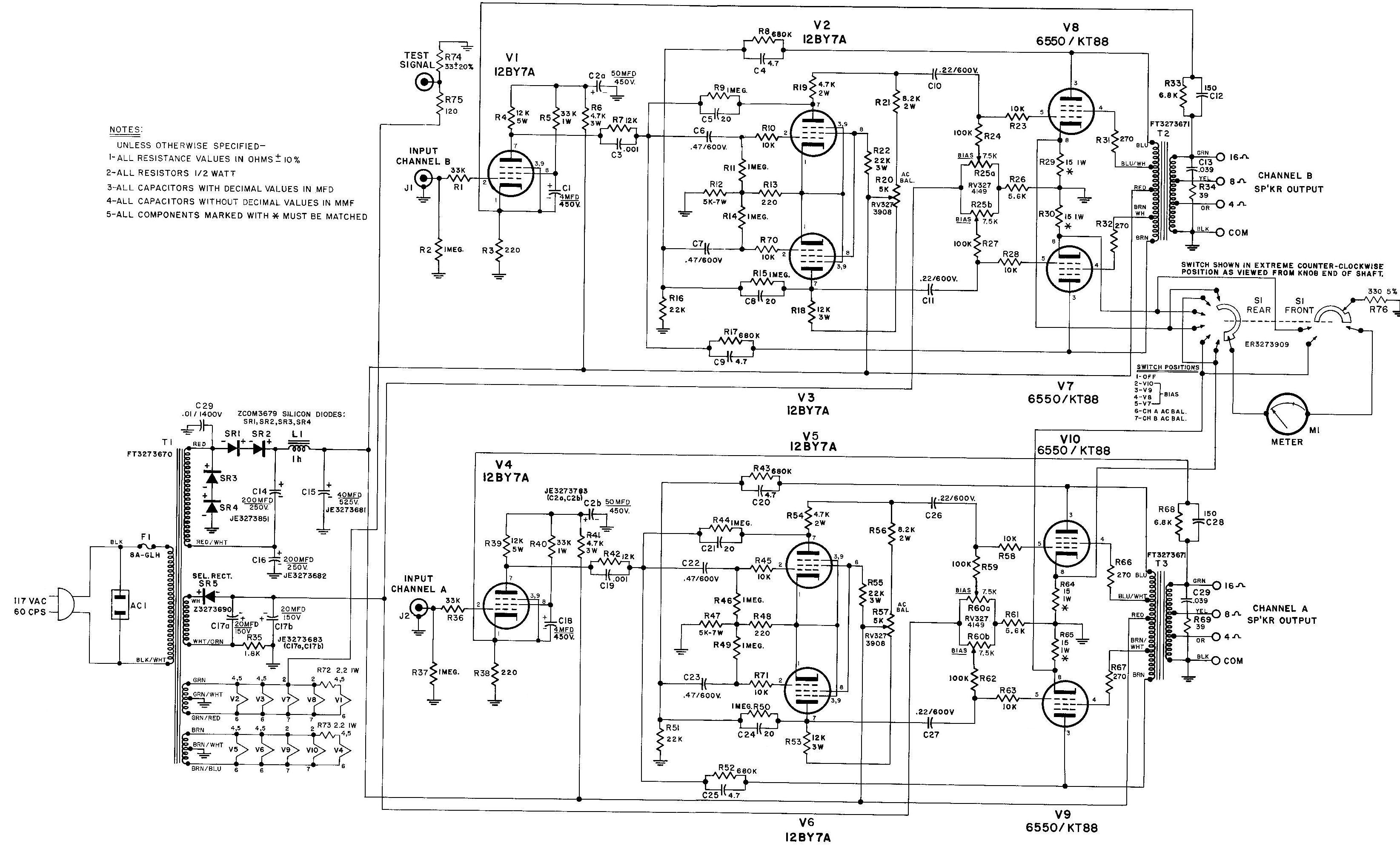
However the Fender 300 PS did use a transformer-coupled 6V6 to slam a quartet of special 6550 to 300 Watts.
Fender 300 PS – Ampwares
http://ampwares.com/schematics/300ps.pdf
However the Fender 300 PS did use a transformer-coupled 6V6 to slam a quartet of special 6550 to 300 Watts.
Fender 300 PS – Ampwares
http://ampwares.com/schematics/300ps.pdf
yes - i want to slam my quartet EL34sFender 300 PS did use a transformer-coupled 6V6 to slam a quartet of special 6550 to 300 Watts.
300w from 4 6550s - how is that possible?
In situations like that, the 6V6 is a driver rather than a phase inverter per se. The transformer does the phasing and splitting. Yes, I am nit-picking, but...
I also see no purpose in using the power tube as a phase inverter.
thanks for nitting - im learning stuff
ehm so i understand - you can NOT send the signal from 6V6 directly in to the EL34s - there has to be a transformer between ? but then - how come there doesnt have to be a trafo after the ecc83 ?
i want to do this because : i do not want any clipping in my preamp stage and my phase splitter stage - i ONLY want clipping in my power amp stage - makes sense to you ?
300w from 4 6550s - how is that possible?
Feed them 700 volts and change them often. I have seen 200 watts from 4 X 6L6GC's. Push them to 250 watts and they blow up. How long will they last?
you can NOT send the signal from 6V6 directly in to the EL34s....One COULD use a pentode as a phase inverter, but WHY?.... is like taking the 1-ton truck to pick up a pizza
You could use a 6V6 for the phase inverter, but it would offer no benefit over a plain jane 6AU6 or any other small pentode. Really want pentodes for a PI, use two of them in LTP. You still don't need a 6V6 though.
If you want everything squeaky clean up to the output tubes, that's fairly easy. Most PI's only distort when overdriven, or when attempting to drive to low of a load, especially through a capacitor (creates blocking distortion). The usual cure is to put a buffer stage, often a cathode follower or mosfet source follower between a standard PI and the output tubes. no 6V6 needed.
The trafo is probably impedance matching, stepping down rather than up. If you want to drive a lot of capacitance, or drive the output tubes into positive g1 current that’s what you do. A 6SN7 wired as cathode followers with half a 12AX7 as a phase splitter would probably work too. Should drive multiple EL34’s as hard as you would want to.
As to how to get 300W out of 4 6550’s? Very carefully. 700 volts and they get very very very hot. I think I would opt for more tubes and a lower Z output trafo.
As to how to get 300W out of 4 6550’s? Very carefully. 700 volts and they get very very very hot. I think I would opt for more tubes and a lower Z output trafo.
You need to know more about "clipping".
The hard-stop clipping is power tube bottoming. An ideal device would pull its end of the OT from (say) 400V to Zero V. A real tube can only pull-down to say 60V, which is still "most" of 400V.
Most drivers (cap-coupled) will not pull the power tube grid positive. In a properly designed and loaded output stage, this happens slightly "after" the plate has bottomed.
As tubelab says, all tube amp drivers will take the grids to this point.
If the driver can try to go to twice that point, the coupling cap charges-down, de-biases the power tube to low-low current, "grid blocking". When blocked the amp "faints" after a loud transient, goes silent for a part-second of the note decay until the bias recovers. Skilled players (Neil Young) can play right on this edge to interesting effect.
The Fender Bassman "longtail" can easily reach this point, and is 93% symmetrical and the maximum drive level can be tuned to just shy of, or just past, grid blocking.
The 300PS is a very special amplifier. And not well-loved then or now. It is the most power you can get from receiving tubes. But the transformer drive does not give the same bark/bite as the cap-coupled drivers used in 99% of guitar amps since the 1930s. It "seemed like a good idea" at the time because (what many present fans do not understand) tubes today are much cheaper, in real money, than ever before. In terms of flipping burgers, prices in 1970 were maybe twice what they are today. So maximizing output per bottle was one way to go. The real limits on 6550 abuse relate to stray grid current when pushed hard. The transformer drive absorbs the DC current and allows significant positive peaks. (OTOH it was beastly expensive even then... it was a pet project, not intended for mass sales.) I don't see much point in this path.
One COULD use a pentode as a phase inverter, but WHY?
because i want endless headroom in my preamp and splitter - no clipping!!
but i want to be able to smash the f# outa my power tubes
Most drivers (cap-coupled) will not pull the power tube grid positive. In a properly designed and loaded output stage, this happens slightly "after" the plate has bottomed.
As tubelab says, all tube amp drivers will take the grids to this point.
well - maybe so - but in my 1970 super lead - preamp will start to clip when i dial volume to 6
in my 1972 fender super rev - same thing
so we DO have a problem here...
well - maybe so - but in my 1970 super lead - preamp will start to clip when i dial volume to 6
in my 1972 fender super rev - same thing
so we DO have a problem here...
No, you have a problem . Both amps were designed so that the output clips before the input. Did you scope the amps to see what is happening? Seems 6 on the dial is fairly normal as to where an amp should clip at.
Pentode PI
Last edited:
Both amps were designed so that the output clips before the input. Did you scope the amps to see what is happening?
hi printer - thanks for the diagram.
i am aware that my good old marshall amps start to clip in the power section before clipping in the preamp. BUT they also do clip in the preamp. i do not know of any vintage amp that does not do that - if you do please tell me.
i know this because
1 i can hear it
2 have experimented alot with attenuators, master volumes, power amp direct ins - preamp direct outs - on quiet a few different amps in my time.
dont tell me that if you take your beloved bassman and turn evering up to 10 - that you do not get clipping in the preamp ?
because i want endless headroom in my preamp and splitter
This discussion was about the driver, and leadbelly mentioned a pair of 6V6's in LTP will supply ample drive. Grid blocking (AKA blocking distortion or farting out) will still occur, only much worse, if this driver is coupled to the output tubes with the typical capacitor.
It is possible to DC couple an LTP to the output tubes, but this is not easy to do without multiple power supplies, so some sort of buffer is needed. The easiest is a cathode follower or a mosfet source follower between the actual PI and the output tubes.
Once a follower is inserted between the PI and output tubes, the PI can be optimized for clean VOLTAGE drive, and the follower can be optimized to supply clean grid CURRENT. The PI could be any tube that can make clean voltage with ample headroom. It could be triode or pentode, and even a pair of 6V6's if you like.
If you want to drive the grids out of your power tubes without distortion then every stage from the input jacks to the power tube grids needs to have enough headroom to allow this. This means that simply copying a 1970 Fender or Marshall preamp schematic will not do, especially if you are going to hammer it with a pedal board.
This means fairly low gain, or at least a means to reduce the gain (multiple "volume" controls) such that a guitar, or pedal board at the amp input can push the PI hard enough to deliver a hundred CLEAN volts or more of signal into the grids of your output tubes.
i want to be able to smash the f# outa my power tubes
There is some power and sound to be found by pushing the "power tubes" beyond the point reachable by the typical wimpy 12AX7 PI coupled to the output tubes by a capacitor.
As stated the typical 12AX7 PI can take the output tubes to the edge of grid current. The common 12AX7 PI will NOT be able to supply grid CURRENT, thus clipping. There are plenty of driver circuits seen in HiFi amps that can go beyond this point into positive grid territory. The driver transformer seen in the Fender 300 watt design is the oldest method.
Venturing into the positive grid area will gain power output by allowing the output tube to saturate deeper by pulling its plate down closer to zero volts. Once this point is reached there is nothing more to gain since the tube can not conduct any harder. Attempting to push it harder will still increase the grid current and may cause tube damage.
I have designed a driver board primarily for HiFi use, and I have explored its use in extracting big power from small tubes. I am not afraid to push tubes to their limits and beyond, and in doing so blow up a few tubes. I have found that when you attempt "to smash the f# outa" a 6L6 type tube it will arc over (internally spark out, fireworks style) somewhere in the 100 watts per pair region. I blasted a couple of 75 year old 6L6GA's into oblivion in testing, but I was using some junk parts that I didn't mind destroying. So there is a point where too much drive will blow stuff up. Some means of limiting the fun before the fireworks set in and this REQUIRES some limiting action (clipping) in the driver. Often the resistor between the driver and the output tube grid can provide this limiting.
There is however quite a bit of room between enough drive to fully saturate the tubes, and "fireworks." At least this is the case with most of the tubes that I have tested. I have not attempted to find the breaking point on expensive tubes.
The driver I built used a twin triode and a mosfet follower. I used a 6CG7. A 6SN7, or even a 12AU7 will also work. I have a similar driver design that used a pair of small pentodes, and I'm sure that it could be made to work with a 6V6, but I haven't tried it. I'm using cheap TV tubes that cost $1 each.
- Status
- This old topic is closed. If you want to reopen this topic, contact a moderator using the "Report Post" button.
- Home
- Live Sound
- Instruments and Amps
- 6V6 splitter