Hi There,
This is probably a big ask but I hoped someone could help me figure out where the hum is coming from on my DIY guitar amp. The hum/buzz is there when no guitar is plugged in (self grounding jack) and increases when I turn up the volume which leads me to think it's coming from somewhere before the volume pot, see schematic. I have tried moving lots of stuff around to no avail.
Background on the amp:
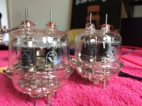
I'm new to amp building and only know what I've read/watched on the internet (mostly Uncle Doug). I had a practise run with a Champ kit from ampmaker.com. The goal was to make a Fender Twin but shrunk down and using these cheap old Soviet tubes (pair of GU-32s) readily available on eBay. It ended up being closer to a Deluxe but grid biased with four power tubes as the GU-32s are dual pentodes.
The amp otherwise sounds amazing, so much better than I had thought and the buzz isn't really noticable when I'm playing but when I stop it's annoying.
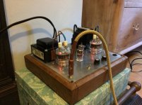
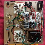
It's all mounted to a sheet of aluminium which is screwed to a wooded frame. I tried to shield as much as possible in an attempt to remove the buzz. I have attached an up to date schematic as it has changed so much plus pictures of the wiring. I tried doing a layout diagram but it was such a mess I included a picture of the inside.
Again I know this is asking a lot but I'm hoping it sparks someones curiosity.
This is probably a big ask but I hoped someone could help me figure out where the hum is coming from on my DIY guitar amp. The hum/buzz is there when no guitar is plugged in (self grounding jack) and increases when I turn up the volume which leads me to think it's coming from somewhere before the volume pot, see schematic. I have tried moving lots of stuff around to no avail.
Background on the amp:
I'm new to amp building and only know what I've read/watched on the internet (mostly Uncle Doug). I had a practise run with a Champ kit from ampmaker.com. The goal was to make a Fender Twin but shrunk down and using these cheap old Soviet tubes (pair of GU-32s) readily available on eBay. It ended up being closer to a Deluxe but grid biased with four power tubes as the GU-32s are dual pentodes.
The amp otherwise sounds amazing, so much better than I had thought and the buzz isn't really noticable when I'm playing but when I stop it's annoying.
It's all mounted to a sheet of aluminium which is screwed to a wooded frame. I tried to shield as much as possible in an attempt to remove the buzz. I have attached an up to date schematic as it has changed so much plus pictures of the wiring. I tried doing a layout diagram but it was such a mess I included a picture of the inside.
Again I know this is asking a lot but I'm hoping it sparks someones curiosity.
Attachments
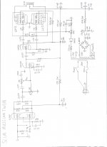
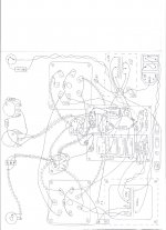
I see the center tap of the output transformer is fed via some 100k resistor from high voltage - which certainly is an error of your schematics. After the first error found in a schematic, I do not trust the rest of the schematics.
There is a plethora of things that can go wrong within an amp - but if you want help here your documentation must be absolutely error free.
There is a plethora of things that can go wrong within an amp - but if you want help here your documentation must be absolutely error free.
I see the center tap of the output transformer is fed via some 100k resistor from high voltage - which certainly is an error of your schematics.
It is 100R, not 100K.
sorry, but I read 100k/5WIt is 100R, not 100K.
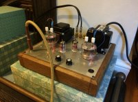
The shield for the input cable is earthed at the socket and heads to a switch which continues the earthing conductor on to the valve in a green sheathed cable. What happens to that earthing conductor at the valve end? Can't see it from the picture.
Also, how many grounds go to that chassis? I can see the one that goes to the speaker earths. It is kind of poor form to have that input ground going across the whole chassis plate to the speaker terminals and then up to the power supply. Far too many signals can be induced into that chassis.
Also, how many grounds go to that chassis? I can see the one that goes to the speaker earths. It is kind of poor form to have that input ground going across the whole chassis plate to the speaker terminals and then up to the power supply. Far too many signals can be induced into that chassis.
Agree-- multiple bonds to chassis "can" work but NEEDS either deep thought or hours of cut/try experimentation.
I am not too proud to admit to "thinking with wire-cutters and clip leads" on one major project. A guitar amp is a LOT more gain than my DA box and more prone to tiny ground currents.
The heater wiring seems UN-twisted? The current fashion is to go to the small tubes with twisted pair and open-up just enough to go to the heater pins, while keeping heater lines down to chassis and signal leads high above (or vice versa).
The preamp tube looks AWFUL close to both the ripple-filled power filter caps and the signal-filled power tubes. Aside from 120Hz just inches away, I'm surprised the thing does not scream from last-plate signal sneaking-back to early grids. "Usually" best practice is to lay-out in a line from small to large signals. Like segregating your septic from your well.
I hate to say it, because it is BEAUTIFUL, but it may take a through re-lay-out to get all the buzz out.
I am wondering why all the caps and resistors are up on the power supply board! Going back to my valve apps in the 1960s and 70s it was always keep everything in order ... Old equipment had each stage's input stuff either wired directly to the valve pins or to terminal strips, and similarly with output. Then power ran clear.
That input jack would be isolated from chassis and the ground would come up the screen. from near the valve input circuit.
The filament wires would be twisted and tight to the chassis and valve socket metal rings. Preferably those filaments would be from a centre tapped supply and the centre grounded to chassis.
It really should look like a linear process ...
Input ~ -> Input filtering -> Valve-> output components > input components -> Valve -> Output
+ve power to one side.
earth to the other
Separate low power earth from high power earth each goes separately to a star earth point where it meets the earth from the power supply.
Don't treat the ground and +ve buses as "connect to anywhere on its length"
Those are physically small caps for their application. They may have the voltage rating required, but I do have to wonder if they've got the ripple current rating!
All these things have to be considered to ensure that you keep hum/buzz out of amps at all frequencies, let alone audio.
I can commiserate with you since designing and building a high gain guitar amp. of my own. I spent almost as much time building it as getting rid of mains hum by eliminating an unnecessary ground loop.
My two cents:
.01) try different grounding scheme. I know this is vague but re-routing or star grounding, or adding a 10R resistor somewhere can do wonders. Also, ground at the end of the chain rather than at the beginning.
Drawing a ground-only diagram may reveal an unnecessary ground or some other snafu.
.02) Rotate the power transformer 90 deg., then another 90 deg., then one more, checking each time.
Bonus third cent: Every conceivable connection, including solder joints and tube sockets/pins must be perfect.
Wow! Great responses guys. I’m surprised you could make anything out from the picture. Thanks.
I’m taking the general consensus is that the problem is layout based. Due to my incompetence it ended up being smaller than I originally planned thus everything is compressed and why the board covers the second preamp tube socket.
I’m going to continue to move stuff around, mainly the grounds. As you’ve figured I have just used the chassis as a here-there-everywhere ground. If I can’t get it to reasonably low hum I’ll grab another sheet of aluminium and start clean taking what you guys said into account. Although it’s going to be hard pulling it apart having worked so hard.
I haven’t got a free weekend for a while so it’s not going anywhere for now.
On the note of the heater wires, I found it difficult to twist them effectively as the power sockets are so large and the heater pins are on opposite ends so I shielded them. Do you guys think this would add more noisy signals to ground?
Again thanks the great advise.
I can't see any ground reference for the heater circuit. If there is no centre tap on the heater winding of the power transformer, you can create an 'artificial centre-tap' with a couple of resistors.
Good observation. Here's an excellent commentary on heater grounding:
The Valve Wizard
Twist is best ... take two strands, put two ends in the chuck of a hand drill and tie the other end somewhere, then turn. It will create a good tight twist. At each tube, run tight to about 1/4" of the nearest pin, then snake AROUND the outside of the socket to the other pin, keeping the wire TIGHT to the chassis.
You can run the two low power triodes on one feed and the GU32's on another feed. I see you're running the filaments on 6V. Don't run the filament return through the chassis. Those GU32's are high current filaments at about 1.6 amps each, so you want to keep that away from the triodes. Remember that the em coupling is higher with higher current. So the steel components in the triodes will pick up from the GU32 heaters ... keep their filament wires AWAY from those triodes.
If you can create an artificial ground as Malcolm suggested above, then great. If not you could ground one side AT SOURCE as an experiment.
As you can see if you read that piece by "The Valve Wizard", there's an element of different strokes for different folks ... His pictures of what to do at the valve socket is definitely different from what I do. The idea of taking the wires across the socket looks like the perfect way to induce EM currents into the neighbouring pins! I take mine around the socket, avoiding the input circuitry by trying to bring those in from clear of the socket.
But I think we're all pretty much agreed that the current layout is liable to introduce problems like you're having.
But I think we're all pretty much agreed that the current layout is liable to introduce problems like you're having.
That's the ticket. I have now added an artificial centre tap and the buzz is completely gone! Thanks Malcom, good spot.I can't see any ground reference for the heater circuit. If there is no centre tap on the heater winding of the power transformer, you can create an 'artificial centre-tap' with a couple of resistors.
Happy ending.... oh no wait, I decided to move some of the ground connections around and ended up melting the insulation on a wire and not noticing. Turned it on, shorted the HT winding and burnt out an expensive power transformer.

- Status
- This old topic is closed. If you want to reopen this topic, contact a moderator using the "Report Post" button.
- Home
- Live Sound
- Instruments and Amps
- Where's the Buzz Coming From - DIY GU-32 Guitar Amp