"Disclaimer": I didn't post this in the "Musical instruments" section because, despite this being a guitar amp, these issues are more of a solid-state / stability and/or circuit design thing, rather than instrument-specific thing.
So, i bought the (faulty) electronics out of a Randall RG200G3 guitar combo a few years ago, and at the time, determined that one of the output transistors had failed shorted.
Here's the kicker: the power amp employs lateral MOSFETs (@SK1058 & 2SJ162)
You can find the schematics over here.
Finding replacements that 1) can be had, 2) aren't fakes, and 3) don't cost an arm and a d*ck was about as successful as finding hen's teeth, as you might imagine.
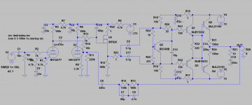
So recently i got a devious idea - retrofit a more conventional BJT output stage. I "mocked up" the circuit in LTspice, and got a seemingly working option easily enough. I then whipped up a board in Eagle, then drilled & scored the PCB in an afternoon.
I went with some free OnSemi samples i got ages ago - MJE15032/33 drivers, and MJW21195/6 output transistors. All was well, until i got to the biasing stage. As soon as i approach the "optimal bias" area (ie. around 2V across the Vbe multiplier), the thing breaks into oscillation
Preemptively, i had already added a 100pF drain-to-gate cap across the MOSFET source-follower that drives the power stage (since "even" the simulation broke into oscillation without that), but that doesn't seem to have helped much.
Attached you'll find the schematic of the power section (screenshot and LTspice file), as well as the (zipped) triode library.
I'd dearly appreciate some thoughts and ideas
So, i bought the (faulty) electronics out of a Randall RG200G3 guitar combo a few years ago, and at the time, determined that one of the output transistors had failed shorted.
Here's the kicker: the power amp employs lateral MOSFETs (@SK1058 & 2SJ162)
You can find the schematics over here.
Finding replacements that 1) can be had, 2) aren't fakes, and 3) don't cost an arm and a d*ck was about as successful as finding hen's teeth, as you might imagine.
So recently i got a devious idea - retrofit a more conventional BJT output stage. I "mocked up" the circuit in LTspice, and got a seemingly working option easily enough. I then whipped up a board in Eagle, then drilled & scored the PCB in an afternoon.
I went with some free OnSemi samples i got ages ago - MJE15032/33 drivers, and MJW21195/6 output transistors. All was well, until i got to the biasing stage. As soon as i approach the "optimal bias" area (ie. around 2V across the Vbe multiplier), the thing breaks into oscillation
Preemptively, i had already added a 100pF drain-to-gate cap across the MOSFET source-follower that drives the power stage (since "even" the simulation broke into oscillation without that), but that doesn't seem to have helped much.
Attached you'll find the schematic of the power section (screenshot and LTspice file), as well as the (zipped) triode library.
I'd dearly appreciate some thoughts and ideas
Attachments
I would put 100pf between Q1 and Q3 bases and their collectors.
I had a similar problem with an amp I designed. The last two transistors cascaded caused the oscillation. Another fix I found was 10R in series with output transistor bases.
It seems the last two transistors in the chain switch on too fast and cause oscillation on the output. Some of the older slower amps get away with it. I had an old Maplin 225WRMS disco amp that worked fine. At least until I put in new transistors and it started oscillating. Increasing VAS capacitor, cap between base and collector of driver transistor or 10R in series with output transistor bases are all possible fixes.
It seems the last two transistors in the chain switch on too fast and cause oscillation on the output.
This. You've also changed the loop gain. You've got drop the loop gain below one before your phase gets past about 3/4pi. (I like phase margin)
Either do the math or disconnect the feedback and measure gain/phase at the feedback point with a CRO. Or both
That's a good call. As you might've noticed, "even" the original design might've been a bit "borderline", since the stock output transistors each had a 47pF gate-to-drain.
I'll be giving that a shot later today
On a side-note, i got a couple other semi-related pointers on another forum, the other day. Upon that, i ended up upping the two 10K resistors connected to the drivers to 100K, and dropping the 100K driver source resistor to 50K (piggy-backed a second 100K in parallel), in order to ensure enough current drive.
Also, i did a quick sinewave test last night. Once the output got above a few Vpp, it broke into some relatively low-frequency oscillation. I say low-frequency (as opposed to the MHz-region noticed before the resistor swaps), because something on the amp board even buzzed / squealed audibly, possibly the output inductor. This was with a 4.5ohm dummy-load.
I would put 100pf between Q1 and Q3 bases and their collectors.
- Status
- This old topic is closed. If you want to reopen this topic, contact a moderator using the "Report Post" button.