While there were precursors, the Williamson agitated the move to heavy NFB and real-low output impedance. Original Williamson was not UL mode but triode, FWIW; the real reduction in output impedance was huge amounts of NFB. The wide use of similar amps supported the High-Fidelity move to "Acoustic Suspension": small sealed boxes with highly damped woofers and (sorta for the first time) easily predicted bass response.
2nd Gen Ampeg VT-40 is zero NFB, still gets wide-range response, but allows the dynamic loudspeakers to bump-up in bass (to compensate the open-back cabinet, which further cuts the hum of PCB heater leads...)
Several of the VERY high-power guitar amps were UL mode. It appears that some tubes and loading conditions will make higher sales-sheet power this way while still being robust in stage work. They are notorious for being LOUD without any graceful edge-of-overload tone, and many are un-loved today (also because today's backs can't lift 130 Watt tube amps).
You don't have to explain how to measure power. I've measured power output many before, I have some amps which basically put out the same power into 4 or 8 ohms. Some amps will prefer 16 ohms over anything else. You may be calling it high impedance reflected to the primary but what does that number tell you and how is it useful? Seems like a useless number.
Please re-read, that's not what I explained. I explained how to measure the output impedance of an amp, not output power.You don't have to explain how to measure power.
No, we are talking about source impedance of the amplifier, at the transformer secondary, not primary.You may be calling it high impedance reflected to the primary
It tells you how much the bass and treble response of the loudspeaker gets modified by its interaction with the amplifier driving it. You can get more details at the link I posted earlier.what does that number tell you and how is it useful?
For the typical non-technical guitar player, yes, it is a useless number. Just as, for grandpa Earl, the diameter of the front brake rotors on his Honda is a useless number.Seems like a useless number.
ggidzinski is not a typical guitar player - in this thread, he is an electronics tech, trying to design a guitar amp + attenuator + speaker to achieve certain specific sonic goals. The amplifiers output impedance has an effect on the sound, therefore, this is useful information to anyone engineering an amplifier.
In exactly the same way, grandpa Earl may find his car's front brake rotor diameter useless information, but his grandson who plans to do some upgrades for more spirited driving will find that information very useful.
I've three times put bigger brake rotors and correspondingly beefier calipers on cars I owned; each time, the difference was substantial, and very welcome. The one that made me really happy was swapping bigger rotors and 4-piston calipers from a 1980s 4WD Toyota pickup truck onto my beater '73 Datsun 240Z. Total brake caliper piston area was the same as before, so I didn't even need to plumb in a new brake proportioning valve. After the swap, the brakes had a much more precise and linear feel that was a joy to experience.
-Gnobuddy
Last edited:
Still doesn't tell me anything. I have built from scratch many amplifiers so i am not new to this and have been a electronics tech for 38 years and still do it for a living today.. Do you have any graphs from a RTA you can show me how this impedance effects sounds, or maybe tell me how you can change this impedance without swapping transformers or nfb? So according to this, the output is responsible for the bass and treble response of the speaker. Can you post some output impedance of common amplifiers such as tweed deluxe, champ, twin, marshalls etc?
... maybe tell me how you can change this impedance without swapping transformers or nfb? …
One way to do it is the pentode/triode switch which some guitar amplifiers include. In triode mode, the amp's output impedance is reduced and the voltage output is less affected by variation of speaker impedance with frequency, giving a flatter frequency response. In pentode mode the output impedance is high and output is boosted at low bass and high treble frequencies (where the impedance of the speaker is higher).
... ... ... ...graphs from a RTA you can show me... ... ... ?
Attachments
By adding a speaker attenuator made from a couple of power resistors, as the OP (ggidzinski) mentions he did in post #34 of this thread....tell me how you can change this impedance without swapping transformers or nfb?
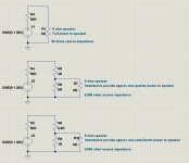
The attached image shows three cases I drew up for you:
1) A guitar amp with 50 ohm source impedance connected directly to an 8 ohm speaker. This is what the amp manufacturer intended. The speaker will produce bass and treble boost due to the 50 ohm source impedance, and this will be the normal sound of the amplifier.
2) A quarter-power attenuator has been added. The attenuator has been mistakenly designed by an engineer, technician, or hobbyist who assumed the amplifier will act as though it has zero source impedance. (This is correct for 99% of today's solid-state amps, but not for valve guitar amps with little or no overall NFB.)
The unintended result: the speaker is now fed by a source impedance of only about 7 ohms, instead of 50 ohms. The speaker will produce less bass and treble. The amp will be 6 dB quieter, but may also sound a bit "blah" because of the reduced bass and treble.
3) A one-sixty-fourth power attenuator has been added. The attenuator has been mistakenly designed by an engineer, technician, or hobbyist who assumed the amplifier will act as though it has zero source impedance.
The unintended result: the speaker is now fed by a source impedance of about 1 ohm, instead of 50 ohms. The speaker will produce less bass and treble. The amp will be 18 dB quieter, but may also sound quite "blah" because of the much reduced bass and treble.
I suspect that at least some of the blame that speaker attenuators get for "tone sucking" comes from this effect. As I mentioned earlier, I have used a dummy 8 ohm load, a resistive voltage divider across it, and then a graphic EQ pedal to derive a line-level signal from a guitar amp speaker signal, which is then fed to a flat-response powered speaker for low-volume home guitar playing. I found that using the graphic EQ to filter out highs above 5 kHz, and to boost bass and low treble a bit, helped me fix some of the "blah" from the reduced speaker volume.
The output impedance affects the bass and treble response of the speaker, yes.So according to this, the output is responsible for the bass and treble response of the speaker.
If you are familiar with any of the software used to design speaker cabs using the Thiele-Small parameters, try adding 50 ohms to the speaker voice coil resistance (Re), and plotting the frequency response with and without the added 50 ohms. You'll see the bass hump up, and if that particular speaker has appreciable voice coil inductance (Le), you'll see the treble response start to climb as well.
Can you post some output impedance of common amplifiers such as tweed deluxe, champ, twin, marshalls etc?
No, I can't; I've never seen that data published anywhere, and as I'm not a tech, most of those amps have never passed through my hands.
What I can tell you: Printer2 measured the output impedance of two of his amps, one single-ended, one push-pull. I think the SE one used a 6V6 and the PP one a pair of 12AB5 (which are downrated 6V6 in nine-pin bottles.) He measured around 50 - 60 ohms in both cases. Neither of these two amps had any global negative feedback.
Fender produces various guitar amps using a PP pair of 6V6's, so you can assume the output impedance of those starts out in the same ballpark, i.e. around 50 - 60 ohms. But Leonidas liked to use some global negative feedback, say 6 dB to 10 dB worth, which will lower the output impedance.
6 dB of NFB will halve output impedance, so gets us to the 25 - 30 ohm ballpark. 10 dB will cut output impedance roughly to one-third, so will get us to the range of 15 - 20 ohms.
Because of Leo's NFB, we can expect small Fender amps to lose less tone as a result of inserting a quarter-power attenuator, than a different guitar amp with no global NFB.
From the datasheets, bigger pentodes and beam tetrodes (6L6, EL34, etc) typically have lower anode resistances. So we can expect them to have lower output impedances, all else being the same.
Not to lose sight of the forest for the trees: the reason I brought up amp output impedance is because adding a speaker attenuator can cause unintended changes in speaker frequency response.
-Gnobuddy
Attachments
Hi Gnobuddy, Im totally with you on the importance of output impedance! I measured my two amps at 20 to 30 ohms (DSL401 and Marshall VM), from 8 ohm taps.
So Ive been designing and testing and analysing resistive attenuators that respect this need to keep output impedance high, and I reckon I can keep consistent tone right down to -27db at which point a 50W amp is putting out about 0.1W. All written up here:
Simple Attenuators - Design And Testing | Page 4 | MarshallForum.com
This is my basic design:
AttenuatorA 180624 | MarshallForum.com
Im targeting a constant 16 to 20 ohms output Z in a series of switched stages. At higher than that , there is not much further change to have since most of the damping is already removed except that which is inherent in the speaker itself.
Very nice work! Thank you for sharing!...I reckon I can keep consistent tone right down to -27dB
<snip>
This is my basic design:
AttenuatorA 180624 | MarshallForum.com
And, I might add, building your attenuator would be a heck of a lot less expensive than buying one of those $$$ Eminence FDM speakers.

I had been thinking about high-Zout attenuator designs too, and I had got as far as doodling a schematic, writing down some equations, and making a spreadsheet to calculate resistor values. But you've done a far more thorough job, complete with measurements. Excellent!
-Gnobuddy
Thanks GnB,
I also started with the assumption that just a couple or three of ohms would make the difference, and I was surprised to find out that guitar amps were so much higher. And I really didn't expect to find that just a resistive system could get so close to keeping the tone as you add attenuation.
The key to the design I use is the reverse L-pad attenuation stages, with the right values to keep consistent Ohms in and out. I keep exploring attenuator schematics online but haven't found any others that follow these principles. The nearest are the AirBrake types, which are a reverse L-pad, but without paying much attention to controlling input and output Z, and often further mixed up with added bleed caps. But the theory is all 19th century, and once you decide on attenuation plus impedance in and out, any resistor network that achieves these three parameters is equivalent.
My current state of thinking on this topic runs like this:
1. Most resistive attenuators are acknowledged as losing tonal balance as attenuation increases, and that this is caused usually by output impedance dropping lower and lower based on conventional L-pad or similar networks.
2. Keeping output impedance correct, in a purely resistive design, solves at least 80 to 90% of the tonal issues that in other designs, are solved much more expensively by reactive loads and re-amping etc. Instead of adding reactive components, this approach uses the natural reactance of the actual speaker.
3. But there must be SOME difference in tone and dynamics of such an attenuated signal and a fully connected speaker, since as the power-amp output characteristics change as it gets overdriven, it is interacting with resistors rather than more complex impedances. So at this time, I'm moving on to try to see what can be added with some inductive components in the design.
Having grown up with transistor electronics, it never entered my head until a year or so ago, that valve guitar amps have high output impedances....was surprised to find out that guitar amps were so much higher...
Once I realized that, it occurred to me that I could take the anode impedance of the output valves, step that down through the output transformer, and so get an idea of the amp's output impedance.
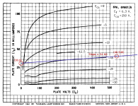
So I drew straight lines on a set of 6V6 characteristic curves, and from the slope, estimated 54 kilo-ohms anode resistance, with the valve operating at fairly typical guitar-amp conditions (350 - 400 volts, around 30 mA). Pic attached.
Taking an 8 k: 8 ohm push-pull output transformer as typical, that's a 1000:1 impedance stepdown ratio. But one valve sees only half the primary, so that's a 250:1 impedance ratio (impedance ratio is turns ratio squared, half the winding equals one-quarter the impedance.)
So if we now take 54k and divide by 250, we get an estimated output impedance of 216 ohms.
If we remember there is a second 6V6 on the other end of that OT primary, and both 6V6s are operating for small signal swings (class AB), that drops to 108 ohms. Still shockingly high.
It turns out that my quick-n-dirty calculation is still off by a factor of two, and the real output resistance is around half of what I calculated. Printer2 measured about 50 ohms on two smallish guitar amps, and so did you.
I don't know why there is a factor of two error (actual guitar amp screen voltage much higher than screen voltage on the characteristic curves I used?), but I'm happy the quick estimate at least got to the correct order of magnitude.
I got that far, but Rout starts to get very high for higher attenuation levels. You fixed that by using a "Pi" network of three resistors when going to higher amounts of attenuation. I didn't.The key to the design I use is the reverse L-pad attenuation stages,
I really like two more of the ideas you used: boosting the attenuated signal back to original level for an A/B listening comparison, and taking an actual FFT of both direct and attenuated signals to see what frequency response changes the attenuator/speaker combination created.
-Gnobuddy
Attachments
I have a cold and my brain (insert "brown pyramid" emoji here) is not working but you've made some assumptions about what each plate is seeing and I _always_ get that wrong by a factor of two.It turns out that my quick-n-dirty calculation is still off by a factor of two,
Find RDH or similar. That will quickly point out why.
Sorry to hear it. Hope you feel better soon!I have a cold
It may be that PRR has already solved the mystery (post #52).
I have a PDF of RDH 4th ed., will take a look and see if I can find what else I'm missing somewhere in those 1200+ pages.
As an aside, studies show (and my experience agrees) that reading comprehension suffers when reading a book on an electronic screen, rather than having physical pages that are tangible in your hands. When the book is as thick and as densely technical as RDH, I find this dramatically true. Sadly, I'm not in a position to print out this many pages on paper, so the PDF will have to do!
-Gnobuddy
Thanks GnB,
I also started with the assumption that just a couple or three of ohms would make the difference, and I was surprised to find out that guitar amps were so much higher. And I really didn't expect to find that just a resistive system could get so close to keeping the tone as you add attenuation.
The key to the design I use is the reverse L-pad attenuation stages, with the right values to keep consistent Ohms in and out. I keep exploring attenuator schematics online but haven't found any others that follow these principles. The nearest are the AirBrake types, which are a reverse L-pad, but without paying much attention to controlling input and output Z, and often further mixed up with added bleed caps. But the theory is all 19th century, and once you decide on attenuation plus impedance in and out, any resistor network that achieves these three parameters is equivalent.
My current state of thinking on this topic runs like this:
1. Most resistive attenuators are acknowledged as losing tonal balance as attenuation increases, and that this is caused usually by output impedance dropping lower and lower based on conventional L-pad or similar networks.
2. Keeping output impedance correct, in a purely resistive design, solves at least 80 to 90% of the tonal issues that in other designs, are solved much more expensively by reactive loads and re-amping etc. Instead of adding reactive components, this approach uses the natural reactance of the actual speaker.
3. But there must be SOME difference in tone and dynamics of such an attenuated signal and a fully connected speaker, since as the power-amp output characteristics change as it gets overdriven, it is interacting with resistors rather than more complex impedances. So at this time, I'm moving on to try to see what can be added with some inductive components in the design.
Just an update, Ive now built and tested a reactive version of my resistive attenuator. With this, the amp is now seeing an impedance that rises with frequency, like a speaker. But Ive arranged it so calculated tone from a clean amp is not affected (since that was already good). Design and A/B tests here:
Simple Attenuators - Design And Testing | Page 6 | MarshallForum.com
The idea is that this test will show up the effect of the amp reacting to the reactive load, seperate to the speaker reacting to a high output impedance amp.
I was surprised by how little difference there was.
- Status
- This old topic is closed. If you want to reopen this topic, contact a moderator using the "Report Post" button.
- Home
- Live Sound
- Instruments and Amps
- Guitar push pull amp OT primary impedance