My first guitar build was a single ended octal power tube based on an AX84 design. Everything went well and the amp sounds great. I understood the OT selection for SE no problem and I can reverse engineer common topologies and data sheet recommendations, also no problem. It appears that using (plate voltage-cathode voltage)*2/max tube power rating gets you really close almost every time.
Now I'm working on my first push pull build but I don't understand how to determine the proper primary impedance given tube/power selection and voltages. It appears that the proper calculation involves comprehending the fact that class AB does not run at max power dissipation continuosly but I don't even see a consistent factor across amp manufacturers. If someone is willing to explain this to me, please also get me right on if the impedance is across the plates of both tubes or the impedence from the center tap to one tube plate. I assume that an advertised say 4K OT primary impedance is across the plates, is that correct? I assume in that case that one tube sees half that or 2K in this case?
Thanks,
George
But you don´t, not even the single ended design. Sorry.I'm looking to understand the selection of the primary impedance based on the tubes, wattage, and plate voltage like I am able to do with a single ended design.
George
Design is not done that way, period.
You are fully ignoring tube current capabilities and just considering dissipation.
Proper design means using and reading tube datasheets to know how 3 basic variables are related:
* plate voltage
* plate current
* grid voltage
then you graphically plot a load line optimizing voltage swing from idle (+V) to saturation and current swing, from idle to peak, grid voltage will swing from idle (bias) to 0V if you keep within Class AB1 (or A1) boundaries.
The slope of that load line is plate load impedance; 4X that is plate to plate impedance.
Notice I didn´t even *mention* dissipation so far.
After you did this, you check you didn´t exceed permissible dissipation and if too much, repeat with a "milder/weaker" load until reaching "safe" results.
Of course I don't know how to design for an output transformer, thats why I am here and asking for help. I am presently ignorant on this aspect of design, but not for long. In the world of guitar amps, I am sure that many abominations are performed in the eyes of ultra linear audiphiles because these departures from pure linear amplification are what give us the tone that we seek. The early designers of the most highly regarded vintage guitar amps probably wouldn't last an hour with this crowd and a lot of vintage success was result of trial and error, cost cutting, etc. Hence the rule of thumb selection of components. Some of the best amps don't sound right unless you use an undersized OT that adds saturation distortion. Tubes run out of bounds voltages, capacitors are used for non linear distortion, phase inverters are intentionally unbalanced, etc. There is even a commercial brand called Train Wreck, I assume to highlight this point. There is an art to this process - as impure as it may be.
I still want to know how to design properly so thank you, this will get me started. Some day I want to move up to audiophile design.
George
I still want to know how to design properly so thank you, this will get me started. Some day I want to move up to audiophile design.
George
Yes, push-pull IS different and can be done many ways. At one extreme you put two SE stages in opposition and basically gain lower distortion. At another extreme you bias to cutoff and slam to maximum available current, hoping not to melt in the process.
Back up. The fundamental rule for an SE stage for an Ideal Device is Rl=V/I. If you run 300V and 30mA you load in 10K.
For an Audio Pentode, this is wrong two ways. We can't swing full supply voltage. We can't swing to zero current. It works out that these "errors" are about equal and complementary; 10K is still a good load.
(Power Triodes, subtract rp from RL and it will work, and it isn't fussy, but triodes are so non-ideal that you really should plot or test.)
And of course dissipation is V*I. 300V@30mA is 9 Watts.
We test with Sine waves. If we tested with Square waves we could ideally output all that we put in, 9 Watts. A real Pentode is lucky to do 80% (10V loss on V, 10% shy on I). So 7.2W. However a Sine does not fill all of space and time. Actually half. So a real Pentode amp on Sine test will generally do 40% of dissipation. 3.6W in this example. 5.6 Watts with 6V6 pushed to the SE limit.
...(plate voltage-cathode voltage) *2 /max tube power rating....
"*" is multiply.
"^" is "raised to the power of". (Occasionally "^^" in program-derived parameters.)
This formula makes some sense if you use "^" (shift-6 on my keyboard). It combines V*I and V/I, the ideal relations for an Ideal Device, and close-enough for an Audio Pentode.
Last edited:
Is it safe to say then that the reason that class AB P/P OT design is more complicated than SE is because the tubes have a power dissipation function that is more complex and not static?
Also then it would appear that in SE the correct OT primary impedance is not actually based on the assumption of max power dissipation, say 14 watts for a 6V6 but rather the current/power dissipation for your chosen bias point? If you chose a cathode resistor in a cathode biased stage that gives say 30ma at 350V instead of the theoretical 40ma at 350V then your primary impedance should be 11.7K instead of 8.8K?
Thanks,
George
When I designed my first vacuum tube guitar amp, I was 16 YO, and knew nothing about proper transformer calculations. But never the less, the amp was sweet!
I took a 50W PA output transformer, recalculated, and wound it turn by turn manually, while watching a TV series. When needed a rest, I draw on a paper the number of turns, to continue from that.
How did I calculate that?
A first, I calculated number of turns per volt that I obtained from number of turns for 120V secondary.
Then, I went from the voltage. I had a power transformer from the same PA amp that when rectifying with doubling gave me 300V and 600V.
I assumed that minimal voltage drop on GU-50 would be 70V, so max amplitude I could get on one semi-primary was 530V. From amplitude I calculated effective voltage, dividing 530V by 1.414.
Then I multiplied it by number of turn per volt and got the number of turn per each semi-primary.
The same with secondary, I went from the voltage that I needed to get 50W on 8 Ohm speaker, and multiplied by number of turns per volt.
Easy! No "Cosmic Science", and the amp was sounding the best in the town!
Edit: the donor amp was a soviet crappy TU-50 with G-807 tubes.
Is it safe to say then that the reason that class AB P/P OT design is more complicated than SE is because the tubes have a power dissipation function that is more complex and not static? ...
No. It is just that there are many ways to approach P-P.
You can build a bridge with a single log. The design calculations are straightforward.
You can build a bridge with more than one stick. "Truss". Now you have Choices To Make. Three big sticks? 50 small sticks?
We don't have so many choices in push-pull, but there is a BIG range of possible designs.
The Same Man will hew to the Suggested Conditions in the tube manual. The dead guys earned their salaries on selling tubes, which means giving GOOD working suggestions. I know sanity is rare around here. But the wise adventurer will start by understanding why the Suggested Conditions are good, even when different.
Sorry if I might have come out as harsh, that was not the idea, but to go straight towards the main point, which is to use datasheet graphs.I still want to know how to design properly so thank you, this will get me started. Some day I want to move up to audiophile design.
George
Don´t want to explain the same thing over and over, so will search for some design example I have posted earlier and link to it.
And the Graphic method is, besides classic, generic, suitable both for Hi Fi and Guitar use
The Same Man ....
should be: The Sane Man ....
I think it makes sense to copy existing designs for a while more, rather than re-engineer, but I too know well the allure of putting your own mark on a project. What kind of power range did you have in mind? Do you have a certain set of tubes you want to use? A sound you are going for? If you can fill in one of those we can have a starting point for a more constrained discussion, or reverse engineer an existing design.
If you are more interested in theoretical first then I recommend the Valve Wizard's two articles on load lines:
The Valve Wizard -Single Ended
The Valve Wizard -Push-Pull
The SE article will introduce you to the backbone of this process. That is the process by which we select operating parameters (supply voltage, load, idle current, etc) to achieve a level of compromise between design goals (Power, distortion, tube life, etc). Load lines make it easier to visualize what the tube "experiences" in use. You need to pick a tube type so you know what curve graphs to go get, a reasonable estimate of your supply voltage (Which means go find a transformer first! They aren't infinitly variable), and - if we are talking about tetrodes/pentodes - graphs for the particular screen voltage you intend to use (Because the curves are different depending on the screen). This is usually close to the plate voltage in guitar amps but rarely is that the case on the datasheets.
If you pick a tube and a voltage you can follow the articles above to draw some lines that represent differing loads and see which ones exceed dissipation, what the power output would be, how much current you might need, etc. The reality is that there is a huge margin around what works and until you've built a hundred amps you won't be able to anticipate how some choices might affect sound. If you are using a typical tube type you'll most likely do this exercise and then just go buy what is available anyway. It is worth doing the homework.
Brian
As a starting point, using twice the SE load impedance for a class AB push-pull pair is reasonable. (Both impedances measured end-to-end of the OT primary.)Over simplification, perhaps but (plate voltage-cathode voltage)^2/tube power rating is indeed what I meant in the case of SE.
If the push-pull stage actually operated in pure class A, twice the SE impedance is exactly what you want; each valve sees one-half the OT primary winding, which has one-quarter of the end-to-end impedance, BUT the second valve is driving an equal amount of current into the load. The net effect is that each valve thinks it's driving twice one-quarter of the end-to-end OT primary impedance, i.e., half of it. So pick an OT with end-to-end impedance twice that of an otherwise identical SE stage, and you're done.
For class AB, the description above applies for small signal swings, when both valves are conducting. However, once peak current through one valve reaches twice the quiescent current, the other valve shuts off. With no help from the second valve, the first one now sees just 1/4 of the end-to-end transformer impedance, rather than 1/2 of it. So the load line doubles in slope at this point. (In reality there is some sort of transition as one valve smoothly cuts off, but we can ignore this subtlety and just draw a kink in the load-line starting at the point where anode current is double the quiescent anode current.
Once you've plotted the (kinky) load line on top of the valve characteristics, you may find that the kink causes you to re-think your initial value of primary impedance. But "twice the end-to-end primary impedance of an equivalent SE circuit" is still a good starting point, even if you have to refine it later.
And, as BJosephs said, in the end you are still limited by what is available, so there is no point in doing too much fine-tuning (unless you plan to wind your own transformers, and use a dummy resistive load on the amp instead of an actual loudspeaker!)
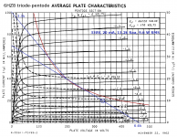
I'm attaching one of my attempts to design a PP output stage using a pair of 6HZ8 pentodes. I came up with an operating point of 20 mA at about 330 volts B+ (easily derived from a cheap 1:1 120V isolation transformer), and an OT primary of 13.2k end-to-end, probably by connecting an 8 ohm load to the 4 ohm tap of an easily available 6.6k OT.
By the way, this entire thread is about the "textbook" way of doing this, or at least near-textbook ways to do it. Go look up some diyAudio posts by Tubelab_com (aka George) if you want to see how it's done by someone who (a)Throws out the rule-book, (b)Really knows what they're doing, and (c) Who has a lab full of the right equipment. George is the guy who regularly pulls two or three times as much power out of the same valves that everybody else uses, without overheating or destroying them in the process!
-Gnobuddy
Attachments
...it would appear that in SE the correct OT primary impedance is not actually based on the assumption of max power dissipation...
Any tube can be run over a range of V, I and load impedance.
Your numbers seem to work for 6V6 at 350V. However a 6V6 can make near the same power at 250V, working higher current and lower Zload. 250V, 50mA, 5K. I have worked a single 6550 over a range of nearly 250V to 600V, with loads from 2.5K to 10K. The difference of optimized power output is quite small.
Thanks, I think I am starting to get it. BTW, I understand needing to keep within safe operating limits to avoid, as George put it - summoning the fire Gods but for us older guys with families, we are actually trying to achieve tone (which needs full throttle) while keeping volume low enough to keep everyone happy. I’m actually looking at push pull stages that use pre amp tubes like in the AX84 firefly or Rob Robinette micro Bassman. At 25 years old and playing in a rock band, I couldn’t afford enough volume. At 65, I generate enough volume for tone and then need to get rid of most of the power before the speaker gets involved without trashing the tone.
Tubelab_com does look like he has done this before.
George
Tubelab_com does look like he has done this before.
George
Last edited:
- Status
- This old topic is closed. If you want to reopen this topic, contact a moderator using the "Report Post" button.
- Home
- Live Sound
- Instruments and Amps
- Guitar push pull amp OT primary impedance