Hi All,
I'm working on a little practice amp that runs in class AB and uses a Long-tail phase splitter. It's wired in a matches/18 watt style (ECC83/12AX7 with equal 100k plate resistors, a 1.2k cathode, 47k tail) driving .022u coupling caps and 220k grid resistors. I'm not using global feedback around the output stage. The negative half of the waveform coming from the non-inverting output (meaning, the plate of the triode that is driven from the cathode, not the master volume) has some very strange non-linearities. It's a class B amp so I don't think any of it is getting to the output but it fascinates me and I was hoping for some ideas as to the cause.
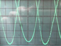
The attached image shows both PI outputs. I swapped probes to make sure it wasn't a scope issue and the distortion did not follow the probes. I disconnected the power tubes as a load and the distortion did not change. I checked my voltages and things seemed rational (big drop across the tail, a couple volts across the cathode resistor, grids a few volts below the cathode). I swapped tube as well (From a new JJECC83S to an old Sovtek from my parts bin) and there was no change. I even changed the cathode and tail resistors to 470/10k like the more conventional splitter used in bigger amps. Then I took this photo (note the imbalance in amplitude due the small tail and equal plate resistors) and decided to post for input.
I have a few days before I can go back to the amp so if anyone has a theory or has seen this before I'd be interested to hear it.
Thanks,
Brian
I'm working on a little practice amp that runs in class AB and uses a Long-tail phase splitter. It's wired in a matches/18 watt style (ECC83/12AX7 with equal 100k plate resistors, a 1.2k cathode, 47k tail) driving .022u coupling caps and 220k grid resistors. I'm not using global feedback around the output stage. The negative half of the waveform coming from the non-inverting output (meaning, the plate of the triode that is driven from the cathode, not the master volume) has some very strange non-linearities. It's a class B amp so I don't think any of it is getting to the output but it fascinates me and I was hoping for some ideas as to the cause.
The attached image shows both PI outputs. I swapped probes to make sure it wasn't a scope issue and the distortion did not follow the probes. I disconnected the power tubes as a load and the distortion did not change. I checked my voltages and things seemed rational (big drop across the tail, a couple volts across the cathode resistor, grids a few volts below the cathode). I swapped tube as well (From a new JJECC83S to an old Sovtek from my parts bin) and there was no change. I even changed the cathode and tail resistors to 470/10k like the more conventional splitter used in bigger amps. Then I took this photo (note the imbalance in amplitude due the small tail and equal plate resistors) and decided to post for input.
I have a few days before I can go back to the amp so if anyone has a theory or has seen this before I'd be interested to hear it.
Thanks,
Brian
Attachments
Last edited:
The negative half of the waveform coming from the non-inverting output (meaning,
the plate of the triode that is driven from the cathode, not the master volume) has
some very strange non-linearities.
Looks like oscillation. Can you post the complete schematic?
A schematic will take some time. It's a bit of a hodgepodge right now and I should double check values before wiring it up so I don't accidentally muddy the waters. I see what you are saying about oscillation - it does look like a higher frequency superimposed on the test tone - but what would cause an oscillation to show up only on one phase output? 
what would cause an oscillation to show up only on one phase output?
That wouldn't be too unusual, could even be lead dress, etc. Photos of the circuit will help also.
Last edited:
I am with you on this oneLooks like oscillation. Can you post the complete schematic?
One thing that occurs to me is that the phasing of any unintentional feedback is positive for only one of the two triodes - and that's the one with the non-inverting output, which is exactly the one experiencing the weird oscillations.what would cause an oscillation to show up only on one phase output?
Of course if it was feeding back to the control grid of the other triode that should be showing some traces of the high frequency signal at it's anode, too, which apparently it's not. Bit of a head-scratcher there.
It may be something else entirely. Perhaps one of the two triodes has higher mu. Perhaps driving it in common-grid mode (drive signal at the cathode) widens its bandwidth, allowing it to oscillate at a high frequency, while the first triode in common-cathode mode has higher Miller feedback, lower bandwidth, and runs out of gain before the frequency gets high enough to cause enough phase shift to oscillate.
Incidentally, I've seen oscillations occur on only one half-cycle of the output in solid-state, class B, complimentary output, power amplifier stages. The asymmetry there is more obvious, since the PNP output transistor is typically slower than its NPN companion!
-Gnobuddy
That wouldn't be too unusual, could even be lead dress, etc. Photos of the circuit will help also.
Pictures will follow as soon as I can get to my "lab". It's point to point so very likely a sloppy wire someplace.
The inverting input has a grid stopper, though I’ve never seen one used on a PI. I added it while debugging some other symptoms. Decoupling is a good idea. I think I hastily ran an alligator clip from the cap to my plate resistors. I’ll try that when I can get back to my bench.
Agreed, but there not be much significance to that fact. I have the distinct impression that many of the things we see in production valve guitar amps were either about cost-cutting, or about lack of technical knowledge, and not about good engineering. Certainly if Leonidas Fender (former accountant) could save a few pennies by omitting a resistor, he would do it....grid stopper...I’ve never seen one used on a PI.
So maybe grid stoppers in the PI are / were not typical production practice. But the PI is still a couple of high-gain triodes - I can't think of a single good engineering reason to omit grid stoppers there.
By the way, I have owned three (valve) Fender guitar amps in the last eight or so years, and all three were just marginally stable. I found that moving a ribbon cable a few millimeters inside a Blues Junior will turn it into an RF transmitter. Replacing the stock output transformer with a better one will make a Superchamp XD oscillate uncontrollably. Simply placing a gain pedal on the floor within two or three feet of a Princeton Reverb reissue will make it burst into high-frequency oscillation. Clearly, none of these amps was properly designed as far as reducing unwanted high-frequency gain is concerned.
-Gnobuddy
Any chance it might be RF pick-up from an intermittent radio transmitter nearby? CB, ham radio operator, etc?...turned it on, and the oscillation didn't appear.
-Gnobuddy
Just to close the loop on this: I wasn't digging the sound with ECC99 finals so I switched to a proper pentode output. To have a chance of being able to use the transformers I already had I found ECL82 which are a combo (little)pentode/triode. I ended up rebuilding the phase inverter from scratch.
- Status
- This old topic is closed. If you want to reopen this topic, contact a moderator using the "Report Post" button.
- Home
- Live Sound
- Instruments and Amps
- Strange Distortion in Negative Swing of Long Tail Pair