Hello,
I have a valvestate 8280 which seems to have a problem with the pre-amp.
No lights on the front panel and it produce no sound via the input jack on the front. The problem just occured after the amp hasn't been used for a while.
I assume a broken cap somewhere but there are no visual damages. Any ideas what to check to identify the problem?
I am not sure I have measured what you suggested.
Since the Pre-amp is feed by power from the transformer I thought that was the only mains input but I see a possibility that the Reverb/PSU feed the Pre-amp as well.
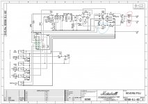
I found a schematic on the net which I included below.
I measued on the Reverb/PSU board.
It is 12VAC in from the transformer.
FS1 and FS2 have high resistance. Don't know which values it should be.
REG1 is possible to move so it needs to be resoldered.
No voltage between pin 3 or 4 and 8 in connector 1(pins on the left hand side).
If high value on FS1 and FS2 indicates that they are gone, can the problem with REG1 causes that?
Replace REG1 as well?
Since the Pre-amp is feed by power from the transformer I thought that was the only mains input but I see a possibility that the Reverb/PSU feed the Pre-amp as well.
I found a schematic on the net which I included below.
I measued on the Reverb/PSU board.
It is 12VAC in from the transformer.
FS1 and FS2 have high resistance. Don't know which values it should be.
REG1 is possible to move so it needs to be resoldered.
No voltage between pin 3 or 4 and 8 in connector 1(pins on the left hand side).
If high value on FS1 and FS2 indicates that they are gone, can the problem with REG1 causes that?
Replace REG1 as well?
Attachments
They seem to be fuses. Resistance should be very low (fraction of an ohm.) High resistance tells you that both fuses have blown.FS1 and FS2 have high resistance. Don't know which values it should be.
Without seeing photos, I have no idea. Are you seeing that the solder joints that hold REG1 to the PCB have actually let go? Or is REG1 still firmly soldered to the board, but there is a loose screw holding it to its heatsink? Are you seeing other evidence of damage (burned smell, charred board, etc)?REG1 is possible to move so it needs to be resoldered.
Since the fuses that supply power to the board are blown, this is to be expected. You won't find any voltage anywhere on the board till the fuses are replaced, and the fault fixed so they don't blow again.No voltage between pin 3 or 4 and 8 in connector 1(pins on the left hand side).
Failure of REG1 could blow both fuses, but it is not the only possibility. For example, a failure of IC1 could also blow both fuses.If high value on FS1 and FS2 indicates that they are gone, can the problem with REG1 causes that?
Replace REG1 as well?
I can't see what you're seeing since there are no photos - but if you're very sure that REG1 has been damaged, then certainly replacing it is a good step to take. Just be careful not to damage anything else in the process of replacing it!
-Gnobuddy
I will post picutres when I am home again next week.
It is possible to wiggle the REG1 a little so the solder seems not to be firm any more.
I need to remove the PCB to study the solder more closely.
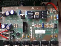
There are no heatsink for these components.
I do not see any other signs of that there are any problem with the PCB.
So, I do not know if REG1 is damaged or has casued the blown fuses.
It is possible to wiggle the REG1 a little so the solder seems not to be firm any more.
I need to remove the PCB to study the solder more closely.
There are no heatsink for these components.
I do not see any other signs of that there are any problem with the PCB.
So, I do not know if REG1 is damaged or has casued the blown fuses.
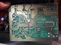
Good starting point, at a minimum, those solder joints need to be heated up and re-flowed.Solder crack is close up on the Reg1 solder there cracks are visible.
The big question is why those joints failed. Did the regulator overheat enough to unsolder itself? Or was there some heavy physical strain placed on it (vibration, bending, etc) that cracked the solder joints? Did it repeatedly overheat and cool, so that thermal cycling cracked the solder joints?
There may be a clue in your sense of smell: sniff that area of the PCB. Does it smell burned or charred?
If there is evidence of overheating, you might consider replacing that regulator. But the other question then is, why did the regulator overheat? Did something else on the board draw too much current?
I suggest using an ohmmeter, and checking between pins 3 and 5 of the TDA2030 to see if they are shorted or not. They should not be shorted - if they are, the IC may have failed, or there is another problem somewhere else on the PCB causing a short between the positive and negative supply rails.
-Gnobuddy
Don't forget the other option: a bad day at the factory.The big question is why those joints failed.
I noticed that, and the PCB markings that suggest the regulator body was intended to lie flat on top of the PCB. No through-hole in the PCB to bolt down the regulator's heat-sink tab, but at least it wouldn't be so tall and prone to vibration.Those regulators are just sticking up from the board, no support.
I wonder if those regulators have already been replaced once?
-Gnobuddy
I soldered something for a work colleague recently, and was mortified when he brought it back with a loose connection. I had made the worst cold-solder joint I've produced since I was maybe ten years old.Don't forget the other option: a bad day at the factory.

-Gnobuddy
I am grateful about your support.
Very appreciated.
I bought it second hand so I do not have the complete story but after some months of use it lost power. It was fixed for free and I was told it was a cold-solder joint. If I remember correct the fan did not start as well.
So yes, it has been repaird before.
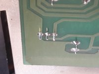
As you see in the pic there are visible cracks at pin 1 and 3. When wiggle the reg pin 1 and 3 moves on the back of the PCB but not pin 2. I removed the reg and as I suspected, pin 2 is broken at the PCB. Interesting that it could work flawless but break next power on.
The value between pin 3 and 5 is aprox 1.9 Mohm.
Could the broken reg pin 2 caused the problem?
Very appreciated.
I bought it second hand so I do not have the complete story but after some months of use it lost power. It was fixed for free and I was told it was a cold-solder joint. If I remember correct the fan did not start as well.
So yes, it has been repaird before.
As you see in the pic there are visible cracks at pin 1 and 3. When wiggle the reg pin 1 and 3 moves on the back of the PCB but not pin 2. I removed the reg and as I suspected, pin 2 is broken at the PCB. Interesting that it could work flawless but break next power on.
The value between pin 3 and 5 is aprox 1.9 Mohm.
Could the broken reg pin 2 caused the problem?
Last edited:
That's good news - firstly it means the TDA2030 is not shorted, and secondly, it also means nothing else is shorting across the power supply, either.The value between pin 3 and 5 is aprox 1.9 Mohm.
I'm with Voltwide and Enzo. If there is no evidence of overheating, just try re-soldering the regulator onto the PCB. It may not be damaged. (You will need to replace the fuses with good ones too.)
I just realized I'm assuming - do you have a soldering iron? Do you have any previous experience soldering on printed circuit boards? Those thin copper traces are quite delicate, especially when they are heated up for soldering, and can be damaged by rough handling. This is another reason to just try re-flowing those two solder joints, rather than trying to remove the regulator completely - it is easy to damage the PCB by using the wrong techniques when removing a part.
-Gnobuddy
I got the parts yesterday since I did not order them directly.
I am not used to work on PCB’s but I have a solering iron.
Thanks for the concern and advice.
I fitted the parts this morning.
24v at the connector and the amp seems to work as it should.
All of you, thanks for the support to solve the issue.
I am not used to work on PCB’s but I have a solering iron.
Thanks for the concern and advice.
I fitted the parts this morning.
24v at the connector and the amp seems to work as it should.
All of you, thanks for the support to solve the issue.
Congratulations! Nothing's better than a happy ending!I fitted the parts this morning.
24v at the connector and the amp seems to work as it should.
-Gnobuddy
- Status
- This old topic is closed. If you want to reopen this topic, contact a moderator using the "Report Post" button.
- Home
- Live Sound
- Instruments and Amps
- No internal power Valvestate 8280