Hi everyone,
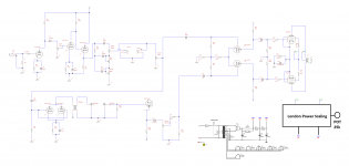
Here I am once more to have one more question on this amplifier that I'm trying to finish over the last few weeks. I attached the circuit to the thread.
The issue that I have here is that when I put all the potentiometers to maximum the amplifier starts to make all sort of loud noises. It sounds like a very bright feedback. This also happens when I put the GAIN more than 7.
The circuit is based on a Marshall 18W TMB, so I was expecting to work properly.
Also, there is a hum that keeps bothering me. I changed the FX loop from an active to a passive one, and it improved. But still not to the level that I want
There is an extra Reverb, FX Loop and Power Scaling. I'm about to remove each item and see where the issue might come from.
Thank a lot for any suggestion
Attachments
I had a similar problem with a guitar amp that had 12ax7's on the front end and EL34's on the output. Part of the problem was simply too much gain. Another problem was signal getting back through power supply to input and causing oscillation. I decoupled each power supply to each valve stage with 10K and 100uF.
Careful pcb layout is important too (if you used a pcb). Keep inputs very short. Use grid stoppers. Use star grounding. Use copper pour around input side connected to ground.
Careful heater layout is important although I only ever used dc heaters once and then found the problem was elsewhere ! Keep transformers and HVAC and heater wiring away from audio signals.
Last edited:
") .
.Look again at the 18W Schematic. http://www.trinityamps.com/wp-content/uploads/2016/08/Trinity-18Watt-TMB-Schematic-v12.pdf You don't have enough power supply nodes. Too many things running from node C in your schematic which will cause "motorboating" form of oscillation when controls are maxed - exactly what you describe.
You should never have more than 2 inverting stages running from any power supply node, the Phase Inverter needs its own node.
Troubles arrise when you have 2 (or more) stages with the same phase from a single power supply node.
Add more powersupply decoupling. Specifically between the Phase Splitter node and the preamp. (R21 and C11 on the schematic I linked) That is the main issue, fix it first BUT You may also need a separate node for the reverb recovery and possibly even a separate one for reverb drive.
Cheers,
Ian
Last edited:
Hi
blackwhaleamp
Gingertube's advice is of great importance and is likely the biggest issue you are facing.
There should also be grid-stops on each tube not just at the input. Grid-stops control the high-frequency response and can stabilise the circuit.
You should get TUT3 from London Power to see the "proper way to wire an amp for lowest-noise and best note articulation" - their words but true once you follow the guide. Re-wired a Marshall using the methods shown in the book and it's the best sounding Marshall me or my friends have ever heard!
I don't see how you will get enough reverb in your amp. The signal coming from the tank is sooooo tiny one gain stage cannot possibly be enough to boost it to a line level for the splitter input?
Also, the cathode of the reverb recovery stage looks like it shares a resistor (and cap?) with a tube not shown. NEVER do this. Give each tube its own bias resistor as this is part of the proper wiring shown in TUT3.
Gingertube's advice is of great importance and is likely the biggest issue you are facing.
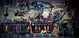
I was going to order one of those TUT3. The advises that Kevin gave me were super useful. As for this amplifier, I realised I forgot to add the cathode resistor at the V3b.
The Reverb signal that enters into the PI is large enough, and I can hear properly the effect.
Also, to reduce the volume I removed the effect loop. I know that my cabling was not great. But the amplifier is quite and the tone is good
Attachments
Also, to reduce the volume I removed the effect loop. I know that my cabling was not great. But the amplifier is quite and the tone is good
That suggests that the effects loop was the wrong type that just has a gain stage running full tilt.
From what I've read, an FX loop should not have any gain really except for the return side. The best loops can do mixing or series and I suspect your loop only does series like the Dumble loop or the one in the 5150? Those all cut the preamp signal down to pedal levels 'cause everyone wants to use pedals in the loop, then you gotta boost it back up to drive the power amp.
In a good loop, that extra gain is there only when you need it and can be bypassed or switched to low gain when you use a processor or there's nothing in the loop.
"excess gain" is good to have in a preamp cuz it gives a feeling of effortless playing. But the loop should not add excess gain or you get noise for no reason.
- Status
- This old topic is closed. If you want to reopen this topic, contact a moderator using the "Report Post" button.
- Home
- Live Sound
- Instruments and Amps
- Loud noise with controls on max