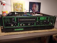
I have this 2x300W bass amplifier on my bench, bought as 'not working'.
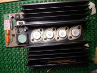
The outputs have been changed obviously, at the moment it has 2x2SK176 and 2xSJ50 on each side. These are not direct complements. 2 K176s are original Hitachi, all 6 others are DSI (a brand that specializes in obsolete components).
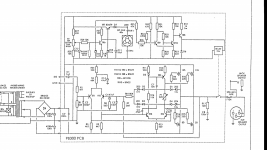
I do not know what was originally in there, I have found a Trace Elliot schematic with BUZ900-BUZ905 in it, but that might be a different revision (schematic seems identical though).
Anyway, are there any dangers running this kind of configuration? I'm afraid there might be some DC offset as Vgs is different? Im also quite sure the transistors haven't been matched, they are used without a source resistor, should that lead to current balancing issues?
Keep in mind, this is a heavy duty bass amp. It should therefore not be very hifi, but it should be very rugged.
Would you keep this config, or change everything to BUZ900/905?
Cheers,
Olivier
Schematisch in attachment.
The outputs have been changed obviously, at the moment it has 2x2SK176 and 2xSJ50 on each side. These are not direct complements. 2 K176s are original Hitachi, all 6 others are DSI (a brand that specializes in obsolete components).
I do not know what was originally in there, I have found a Trace Elliot schematic with BUZ900-BUZ905 in it, but that might be a different revision (schematic seems identical though).
Anyway, are there any dangers running this kind of configuration? I'm afraid there might be some DC offset as Vgs is different? Im also quite sure the transistors haven't been matched, they are used without a source resistor, should that lead to current balancing issues?
Keep in mind, this is a heavy duty bass amp. It should therefore not be very hifi, but it should be very rugged.
Would you keep this config, or change everything to BUZ900/905?
Cheers,
Olivier
Schematisch in attachment.
Attachments
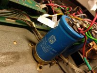
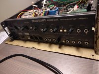
I like the non-existent DC protection. Well it has a fan and relay. 4700uF also seems low for 300W. And if You ever put it in service, please exchange that XLR connector for a Speakon one. What's the rail Voltage ?
Rail is +-70V I believe.
Like I said, it's not a hifi design. I have had 50watt amps with 10mF of cap, but this one only has 10mF for 2x300W. I can get pics tonight.
AFAIK there´s only one Lateral Mosfet manufacturer left: PLC/Exicon in UK.
They make and sell spare MosFet dies (the 6 x 6mm silicon chips thenselves) who are bought by others, encapsulated, and given their own brand.
So *today*, all fresh BUZ, many 2SK/SJ and others "are all the same inside".
So go straight to PLC and get what you need, they do sell straight to the Public and for very reasonable prices.
Their own brand is Exicon .
VERY good stuff , and quite reasonable price, don´t know why Amp manufacturers don´t start using those MosFets again.
Hi, thanks guys!
I will take a look at what Exicon offers.
By the way, the schematic I posted has a parts list with BUZ900/905 in it, but as Enzo says , the numbers next to the symbols probably point to 2SK135 and 2SJ50. These last are probably what used to be in here.
I'll call around to see who stocks any of these. Getting them from Darnell/RS Iis possible but I'll need to find a middle man")
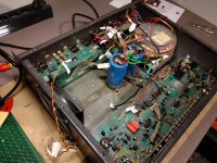
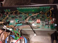
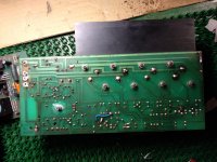
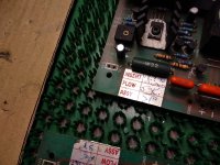
Anyway, here are some pics. Overall, I'm not too impressed. It looks like manual work (apparently "Julian" and "Andy" built this one), even original soldering. Also PCB traces aren't of the greatest quality and like MAAC0 said, there is no DC protection (there is a fuse, but surely something better was available in early 90s..).
Components are of good quality, but then again this used to be a very expensive amplifier. Even now it fetches 500 dollars in good condition.
I will take a look at what Exicon offers.
By the way, the schematic I posted has a parts list with BUZ900/905 in it, but as Enzo says , the numbers next to the symbols probably point to 2SK135 and 2SJ50. These last are probably what used to be in here.
I'll call around to see who stocks any of these. Getting them from Darnell/RS Iis possible but I'll need to find a middle man
Anyway, here are some pics. Overall, I'm not too impressed. It looks like manual work (apparently "Julian" and "Andy" built this one), even original soldering. Also PCB traces aren't of the greatest quality and like MAAC0 said, there is no DC protection (there is a fuse, but surely something better was available in early 90s..).
Components are of good quality, but then again this used to be a very expensive amplifier. Even now it fetches 500 dollars in good condition.
Attachments
-
 IMG_20180612_213926.jpg995.3 KB · Views: 148
 -
 IMG_20180612_213932.jpg922.7 KB · Views: 149
 -
 IMG_20180612_213938.jpg635.8 KB · Views: 139
 -
 IMG_20180612_213948.jpg990.1 KB · Views: 168
 -
 IMG_20180612_213954.jpg839.1 KB · Views: 88
 -
 IMG_20180612_214007.jpg783.8 KB · Views: 109
 -
 IMG_20180612_214038.jpg795.6 KB · Views: 132
 -
 IMG_20180612_214045.jpg779.1 KB · Views: 100
 -
 IMG_20180612_214051.jpg981.4 KB · Views: 112
1200W with 4*100W transistors from 2SK135 datasheet ??. 70V at 4Ohm it's 17.5A, datasheet says 7A. Weird.
Forget the 1200 Watts, thats marketing gibberish. It is 2x300 watts RMS using 2x 2 K135-J50 pairs. So about 6A peak per transistor
A little update:
I finally received the replacements, four pairs of BUZ900/BUZ905. I installed everything, powered it up with a bulb in between. No magic smoke, happy!
Anyway, it works again but it needs biasing. Usually there is a description in the service manual, now there is none. As these are MOSFET outputs, the bias current is set by setting a voltage at the gates of the output transistors. However, I cannot measure the current, as there is no series resistor in the output current branches to measure a voltage over...
I tried by checking crossover distortion, but even at the lowest setting I can't see anything visually (that is, with some shitty car speaker as a load and volume at 10%).
Anyone has hints on setting the bias current on this thing?
No big deal, in this case, because Lateral Mosfets are mild mannered smooth and forgiving Gentlemen (unlike their rough Vertical cousins ), not a big nonlinear jump like them.
Usual instructions are just to set "X" mV base into base, in the order of 100 to 200mV, they don´t even care about actual idle current, but to play it safe, do what some do: you cut the track leading to top MosFet Drains with an X-Acto sharp knife, so you create a 0.5mm to 1mm gap, not wider, scratch solder resist on both sides of the gap so you see shiny copper, turn amp ON , no signal, no speakers or any load and bridge both sides of the gap with your Multimeter probes, set to 200mA scale.
You are now measuring actual current through power MosFets only.
Plan B: you bridge gap using a 0.47 or 1 ohm resistor, 2 to 10W, whatever you have available, and measure millivolts across it, to determine current.
In any case, start with minimum bias setting and slowly rise it until you measure some suitable bias current, say 20 to 35mA per power Mosfet.
Once set, turn amp OFF, pull resistor if you added one, and bridge both sides of the scratched gap with a drop of solder.
Some PCBs already include such interruption for Factory adjustment and don´t even mention it in the schematic, so follow tracks first just in case it´s already there.
), not a big nonlinear jump like them.Usual instructions are just to set "X" mV base into base, in the order of 100 to 200mV, they don´t even care about actual idle current, but to play it safe, do what some do: you cut the track leading to top MosFet Drains with an X-Acto sharp knife, so you create a 0.5mm to 1mm gap, not wider, scratch solder resist on both sides of the gap so you see shiny copper, turn amp ON , no signal, no speakers or any load and bridge both sides of the gap with your Multimeter probes, set to 200mA scale.
You are now measuring actual current through power MosFets only.
Plan B: you bridge gap using a 0.47 or 1 ohm resistor, 2 to 10W, whatever you have available, and measure millivolts across it, to determine current.
In any case, start with minimum bias setting and slowly rise it until you measure some suitable bias current, say 20 to 35mA per power Mosfet.
Once set, turn amp OFF, pull resistor if you added one, and bridge both sides of the scratched gap with a drop of solder.
Some PCBs already include such interruption for Factory adjustment and don´t even mention it in the schematic, so follow tracks first just in case it´s already there.
Last edited:
Hi! Thanks for the reply.
I didn't want to cut the tracks (it would have been quite a nightmare), so I ended up just setting the gate voltage of the N-channels to 0.2V while measuring the total power consumption of the amp.
I calculated it to be about 25 mA of idle current per FET.
Then I did an endurance test, it works without an issue now.
There is still a problem in the preamp (not enough gain) but that's a separate problem, I don't expect it to be a big issue.
Cheers again!
- Status
- This old topic is closed. If you want to reopen this topic, contact a moderator using the "Report Post" button.
- Home
- Live Sound
- Instruments and Amps
- Trace Elliot RAH600SMX, outputs were replaced incorrectly