I've been prototyping a high gain preamp for about month or so now. While I don't have an engineering background, I've been reading/watching everything I can about the topic for months. Most of my time on the bench is spent trying out different plate loads, biases, interstage filtering etc... I've learned a lot, but also am overwhelmed with the complexity of designing a cascaded high gain circuit.
Getting to the point, what influences a designer to use "X" voltage at "Y" stage? What I've noticed with nearly all the schematics I've studied is that they tend to favor high (350V or more) B+. My current PT can only put out about 265V, so I have no way to experiement (cash is tight atm). I understand higher B+ will offer more input headroom and higher output gain. But what about the tone? If I up my supply, say to 375V, will the tone be brighter, punchier, etc?
The main reason I'm curious is that I've notice, no matter what circuit I wire up, there's a noticble lack of upper harmonics and generally the tone feels "flat", or 2 dimensional, sometimes even "choked". My first prototype was a Mesa Rectifier (basically a SLO with a smaller gain pot). This gave me a chance to compare directly with my Triple Rec (which I'm using as a power amp for my pre). The tone and feel was in the ballpark, but the Mesa sounded wide open. My preamp basically reminded me of a distortion pedal. :-(
Anyway, I realize what I'm asking is very subjective, but any tips or suggestions would help. I've gotten pretty far on my own, but before I take the next step (ultimately I plan to build a 20W head for studio use) I need a bit of guidance.
Thanks!")
Getting to the point, what influences a designer to use "X" voltage at "Y" stage? What I've noticed with nearly all the schematics I've studied is that they tend to favor high (350V or more) B+. My current PT can only put out about 265V, so I have no way to experiement (cash is tight atm). I understand higher B+ will offer more input headroom and higher output gain. But what about the tone? If I up my supply, say to 375V, will the tone be brighter, punchier, etc?
The main reason I'm curious is that I've notice, no matter what circuit I wire up, there's a noticble lack of upper harmonics and generally the tone feels "flat", or 2 dimensional, sometimes even "choked". My first prototype was a Mesa Rectifier (basically a SLO with a smaller gain pot). This gave me a chance to compare directly with my Triple Rec (which I'm using as a power amp for my pre). The tone and feel was in the ballpark, but the Mesa sounded wide open. My preamp basically reminded me of a distortion pedal. :-(
Anyway, I realize what I'm asking is very subjective, but any tips or suggestions would help. I've gotten pretty far on my own, but before I take the next step (ultimately I plan to build a 20W head for studio use) I need a bit of guidance.
Thanks!
My preamp basically reminded me of a distortion pedal. :-(
Can you post your schematic?
To get harmonics you need to over drive the valve stage(s).
I gave up trying to get valves to distort like Marshall and used an op amp soft limiter.
I gave up trying to get valves to distort like Marshall and used an op amp soft limiter.
An externally hosted image should be here but it was not working when we last tested it.
Higher voltages will give you a cleaner sound from what I understand. How about using a voltage doubler and a voltage divider to get it down where you want it.
Thanks, I hadn't thought of that. I'm still a rookie
I'll look into it right away.@rayma I didn't post any schematics because my question was more broad. Every circuit I've prototyped, either a commercial design or my own, exhibited the same general symptoms as I described in my post. They sound ok, just lack luster. I narrowed down as many variables as I could so I came here for suggestions (like what Printer2 replied).
@nigel I have no problem coming up with a good/decent sounding, all tube overdrive circuit. I'm still learning, and enjoy the journey of experimentation. One of the variables I havn't tinkered with is higher supply voltage. And Printer2 gave me something to chew on (thanks again).
And with all due respect, I have no intention of using opamps to achieve what tubes do naturally.
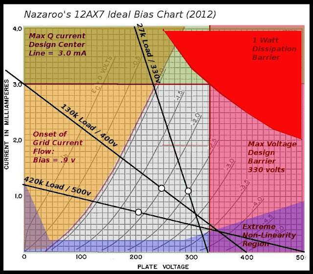
Nazaroo demystifies the 12ax7 biasing well. My aha moment came from orange drops in my bandmaster and and Vishay/Dale RN65 Resistors 100K plates. These days I've found much better caps and the original caps were ancient crap. Maybe try LED biasing or different cathode cap values. play around with cap ratios based on frequencies. I can't remember the book, but it was white with cool hand drawn schemos. And went through cap values to accentuate different notes.
5751's are fun too
Have fun!
I don't mean insult but check these
A Bibliography of "Must Have" Tube Electronics Books
12ax7 perfect bias point
5751's are fun too
Have fun!
I don't mean insult but check these
A Bibliography of "Must Have" Tube Electronics Books
12ax7 perfect bias point
...higher B+ will offer more input headroom and higher output gain.....
B+ has nearly no effect on electronic gain. Going from 300V to 90V may shave 10%, no big deal.
Maximum output, and thus THD at any lesser level, scales almost exactly with B+.
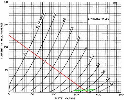
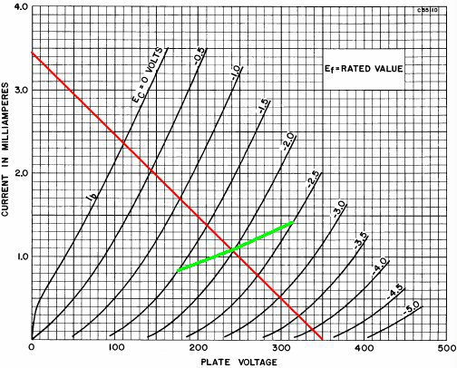
Have you studied the Resistance Coupled Amplifier table published for most of the likely amplifier tubes? The now-dead junior engineers sweated over hot slide rules to give us this useful information. Nearly all the Classic Guitar amps start from those values, though of course Leo and Jim had to put their own mark in their work.
For bipolar junction transistors, B+ voltage does have a strong effect on voltage gain. In fact voltage gain for a good BJT is approximately (40 x voltage_drop_across_collector_resistor). If you have only 1 volt DC across the collector resistor, voltage gain is only about 40 times. If you have 10 volts DC across the collector resistor, voltage gain is about 400 times.
This assumes no additional AC load on the output, i.e. we are studying a single gain stage by itself.
For any sane biasing scheme - either keeping quiescent (DC) collector voltage constant, or at a fixed fraction of B+ - that also means voltage gain is proportional to B+ voltage. (Again, we are talking about BJTs here.)
To a slightly lesser degree, I found the same thing is true for pentodes. Voltage gain is nearly (gm x Rp). If you fix anode current, then gm is fixed, so voltage gain is proportional to Rp.
DC voltage across Rp is (Ia x Rp), so once again, the voltage gain of the pentode is nearly proportional to the DC voltage drop across the anode load. (Once again, assuming no additional loading on the output of the gain stage.)
Triodes are the exception, because of their low internal anode resistance (ra, or rp in American.) There are diminishing returns in voltage gain as Ra increases beyond ra, so increasing the DC voltage across Ra doesn't yield proportional increases in voltage gain beyond that point.
Add in the fact that Ra for a 12AX7 is usually quite large, so loading by the next stage is rarely negligible, and those small voltage gain improvements diminish even more.
From the DIY point of view, and most especially for a valve guitar preamp stage, trying to extract the maximum voltage gain from a stage is rarely a worthwhile goal. Usually we're more interested in extracting the timbre we want - the distortion characteristics that we think enhance our guitar sound - and we can just use as many gain stages as necessary to achieve that result.
-Gnobuddy
I appreciate the replies, everyone. I fully admit that I know (relatively) very little about electronics and vacuum tube circuits. However, I think my questions, as subjective they may be, are being missed. And that's ok. I probably should hit the books and not expect others to give me the "cliff notes".
This is exactly what I'm asking. What effect does the supply voltage have on the timbre when a tube it is overdriven? Does a higher supply produce brighter distortion?
The circuit I'm prototyping at the moment is 4 cascaded stages. It's sounds decent enough and there's no major technical problems like excessive noise, 60Hz hum, oscillations, etc... But it is missing "something" that I can't put my finger on, particularly in the top end. It lacks a certain "sheen" that my other amps exhibit. My B+ is around 260-270V. Most, if not all, schematics (Mesa, Soldano, etc) run 100V or more higher. I'm just curious as to why.
It was suggested above that I build a voltage doubler and try it for myself. I'm still need to order new caps for that, but that is my next step.
trying to extract the maximum voltage gain from a stage is rarely a worthwhile goal. Usually we're more interested in extracting the timbre we want - the distortion characteristics that we think enhance our guitar sound
-Gnobuddy
This is exactly what I'm asking. What effect does the supply voltage have on the timbre when a tube it is overdriven? Does a higher supply produce brighter distortion?
The circuit I'm prototyping at the moment is 4 cascaded stages. It's sounds decent enough and there's no major technical problems like excessive noise, 60Hz hum, oscillations, etc... But it is missing "something" that I can't put my finger on, particularly in the top end. It lacks a certain "sheen" that my other amps exhibit. My B+ is around 260-270V. Most, if not all, schematics (Mesa, Soldano, etc) run 100V or more higher. I'm just curious as to why.
It was suggested above that I build a voltage doubler and try it for myself. I'm still need to order new caps for that, but that is my next step.
No, it just moves the operating point. A key distinction. The question of interest is: what non-linearities are present at that point?Does a higher supply produce brighter distortion?
To use my broadest brush, we're usually picking an operating point down near the dark blue and/yellow bits on Nazaroo's chart so that we rapidly move into some nonlinearities. Consider the operating point of the Soldano third stage - almost off the chart (all blue). This is a 2nd H generator.
(thanks to Ampbook's analysis of the Soldano circuit)
The second stage in the same circuit is placed in a completely different part of the operating curve, and after some initial 2ndH generates a pile of 3rd as the level ramps up. Initially blue, adding yellow a little later.
Nb1: carbon comp resistors are also non linear and will add 2nd H if you have enough voltage across them
Q1a. What makes you think that this "sheen" comes from the preamp stage?It lacks a certain "sheen" that my other amps exhibit.
Q1b. is the only difference the pre-amp voltage? Is the circuit the same? Are all the passive components the same?
While some will point out the audiphooolishness of extreme audiophillia and associated snake oil, our passives are far from ideal. And in ways that can be quite measurable & predictable in simulations.
Mostly because the output stage needs that high voltage. And the designers (more correctly, "incremental tweakers") have no reason to move from the time-honoured way in which the B+2,3,4,5 etc for the preamp is generated. If you've considered Q1b you'll note that this represents a choice that affects the slope of the load line at any particular operating point.Most, if not all, schematics (Mesa, Soldano, etc) run 100V or more higher. I'm just curious as to why.
I think your next step should be identifying which part of the amp is generating the "sheen" you are hearing.It was suggested above that I build a voltage doubler and try it for myself. I'm still need to order new caps for that, but that is my next step.
NB2: if this is a pushpull pentode/tetrode amp in class AB, you are likely getting IMD from power line ripple. That's usually reported as "growl" rather than "sheen". Plane old screen sag will generate some "chimey" 3rd/5th notes
Last edited:
I was struggling with exactly this problem a while ago, and came up with the idea to put a graphic EQ between guitar and prototype guitar amp, and see if I could dial in a better sound. In your case, you might try a little boost above, say, 1 kHz, to see if that gives you what you're looking for.The circuit I'm prototyping...is missing "something" that I can't put my finger on, particularly in the top end.
If you find an EQ curve that gives your amp the sound you want, then the next step is to measure the actual frequency response of the EQ pedal without touching any of the frequency sliders, so you know the actual frequency response you just dialed in to make your amp sound good.
Once you've measured the frequency response, you can then re-create that same frequency response as closely as possible using resistors and capacitors. I use the free LTSpice circuit simulation software to mess about with resistors and caps until I get a close match to the EQ curve I want. Once you have that, build it into your amp, and see if you found the sound you were looking for.
It may happen that fiddling with EQ still doesn't produce the sound you want, in which case you have to make changes to the preamp circuit and try again - the usual fiddling with warm bias / cold bias / interstage attenuation and so on.
It can get tedious, so I try to remember not to get too fixated on the amp, since in the end it's up to my hands and my ears - with some trial and error, I can usually change the way I play my guitar so as to get a reasonably good sound out of any halfway-decent amp.
-Gnobuddy
I'm using the FX return of my Triple Rectifier as a power amp. I'm primarily comparing my proto to my Mesa Studio Preamp. Occasionally I plug straight into the Recto for comparison as well. Either way both the Studio Pre and the Recto (same power section) sound more open, alive, "3D". So the actual design isn't important. I'm hearing a distinct difference in overdrive texture. Mine seems to clip at a lower frequency range, if that makes sense.Q1a. What makes you think that this "sheen" comes from the preamp stage?
Q1b. is the only difference the pre-amp voltage? Is the circuit the same? Are all the passive components the same?
No, I'm not using the components as either Mesa I'm comparing it to. I respect that component choice is important, and part of a designers RnD process. I'm just not so sure what I'm hearing is that. I feel like it is something more specific.
The preamp section is the only part that isn't the same.I think your next step should be identifying which part of the amp is generating the "sheen" you are hearing.
My initial prototype was the preamp section of a Mesa Rectifier. Didn't sound very good. But when I thought I'd figured out why (operating point, like you'd mentioned above), it made sense - the 3rd stage was basically operating at cut off. I drew up load lines and determined 27k would work. When I tried that out, it still sounded mediocre. And well... after months and dozens of tweaks, rebuids and finally my own design, I'm still no closer to figuring it out.
I actually am using a passive tone stack after V1a for that reason - to shape the overdrive's tone to be able to get tight high gain metal to fuzzy blues. And then another TS after the last stage for overall shaping. Think Mesa Mark series.I was struggling with exactly this problem a while ago, and came up with the idea to put a graphic EQ between guitar and prototype guitar amp, and see if I could dial in a better sound. In your case, you might try a little boost above, say, 1 kHz, to see if that gives you what you're looking for.
-Gnobuddy
I'll draw up my current proto schematic and record some sound clips tomorrow. Hopefully it can capture what I'm hearing.
That may do the trick. But a passive tone stack is a blunt club compared to the elegant rapier that is a graphic EQ pedal. The passive stack is only capable of very crude, broad-band changes to the frequency response curve.I actually am using a passive tone stack after V1a for that reason
For best sound, one recent solid-state guitar amp project wound up with a slight bass boost below 400 Hz, a slight notch at 800 Hz, a peak at 2 kHz, and a steep fall-off above that. I could never have found that EQ curve with a passive tone stack, which is not capable of generating such a curve.
(Duplicating that EQ curve also required me to design an active circuit.)
-Gnobuddy
Hi
Conceptually you expect that power supply voltage has little effect on tone but that is incorrect. High voltage tends to provide high clean headroom just as used in the first guitar amps which were really hifi circuits applied to guitar use. The aim was to have clean output.
If you reduce the voltage to those clean preamps, like in a fender amp, the tone will stay clean to a point but things get wierd below 100V. The stock cathode and plate values simply don't work and there is no headroom at all. You have to make major value changes for either the plate or the cathode to get the plate voltage anywhere near centred for equal swing. At that point, the gain is way down but then so is the maximum signal swing, so it balances out.
Keeping the voltages in the usual tube range, say 160V minimum, taking the voltage down from 400V to 200V will warm the sound quite a bit. Distortion will smooth out and depending on the exact values of the circuit the distorted sustain might increase.
Tweaking up or down 5V or 10V is not likely to give you a glorious sound change, but a 50V or 100V change might.
I got The Ultimate Tone books a while back and the first book shows a quick way to tweak each gain stage for maximum sustain. The fifth book has a whole chapter about preamps and there is a way to set up high gain preamps for maximum sustain. You need a scope for that where the first tweak you just need a volt meter. I added some gain to a Marshall and used these methods to set things and it made a huge difference to the tone. The original amp had all this - I dunno - "hash" in the sound - I think KOC called it intermodulation distortion which does not sound good even as a name - haha - but doing the rewire then setting up each stage made the amp totally magnificent - tone from the Gods - or tone from King Tut. Cool!
Just wanted to give an update. I did record some audio clips, but microphones are incapable of capturing the sound and feel of an amp in the room, so I didn't bother posting them. I did however, start a new project: a high gain 20W scratch build. Power amp based of Fender deluxe (pair of 6V6's), preamp based off my own designs. For trannies I went with ClassicTone DR replacements. I also went with diode rectification so my HV would be plenty high to experiement with.
So, I have my preamp HV nodes running pretty high (~425V. As opposed to the ~275V I had on my original preamp). Sure enough, the difference in tone is exactly as I suspected. Crisper distortion, more alive feeling, not "hazy" at all.
Yep, higher supply makes a considerable difference in the distorted tone - a difference that I much prefer. And I suppose that is the point: everyone has their own goals. I'm after modern distortion, not cloning a vintage Marshall.
Congratulations Fozzy. It sounds like you proved Nazaroo’s chart. Did you change the power transformer or just modify B+ dropping resistors?
Thanks bud. I ended up buying a new PT, a ClassicTone 40-18066, which I'm using in a new build I'm working on currently. I'm taking pictures of the process (it's in working condition, but I'm still tweaking the preamp circuit) and I plan to start a new thread about it. Mostly to brag a bit, to help out other newbs, and get constructive feedback.
I'll find a use for the tranny I was originally using (190/0/190). I'm thinking a bass preamp/DI for recording. So I can give the voltage doubler idea a shot.
Cool. Did you happen to get any screen shots (from a CRO) or do you have the operating points? (Va, Vk, Rk, Ra etc)So, I have my preamp HV nodes running pretty high (~425V. As opposed to the ~275V I had on my original preamp). Sure enough, the difference in tone is exactly as I suspected. Crisper distortion, more alive feeling, not "hazy" at all.
Yep, higher supply makes a considerable difference in the distorted tone - a difference that I much prefer.
Cool. Did you happen to get any screen shots (from a CRO) or do you have the operating points? (Va, Vk, Rk, Ra etc)
CRO? I'm unfamiliar with what that is.
No, didn't document voltages, nor calculate load lines. I took preliminary voltage readings to make sure the circuit is operating as intended as I was building each stage. I tuned everything by ear from that point.
- Status
- This old topic is closed. If you want to reopen this topic, contact a moderator using the "Report Post" button.
- Home
- Live Sound
- Instruments and Amps
- Tube Guitar Preamp - Choosing Supply Voltage?