I've been working on a Differential tube mic preamp based on McCurdy au300 and Langevin 5116b designs. The output jack goes to a sowter 9900 transformer at the moment. In this design the output tube is biased so cathodes are at 10.5-11 V when using the cathode resistor and balance pot. But when I use the CCS it seems to be rather high, like 12.5-14.5V. I've tried a bandgap lm385 2.5V as suggested by Merlin B in his book. I think with this circuit, I finally got tubes be receiving about 13 mA between according to a 10 Ohm resistor on the CCS board. But the Cathode voltage seems a bit high at 14.4 and 13.2V, which makes me think that the tube isn't biasing.
My question is whether or not the CCS below will work to bias the tubes at 11V? Morgan jones and others like index seem to do their CCS with negative supplies. But I don't have a negative rail to grab from at the moment.
There should be connections from V2's plates to V3 grid stoppers via a 47nF coupling cap. and B+ is 290V-310V. R11 is omitted when using the CCS.
PS. I browse here a bit and appreciate the wealth of info. Thanks to those who maintain this site
Attachments
Last edited:
Thanks so much Jazbo8. I have another thing that’s puzzling me. I have a 10 ohm resistor at the output of the CCS to measure voltage and read the current. And what’s puzzling me is that even with an Re=732 I am still reading 130 mV which tells me it’s outputting 13 mA. Right? I thought I should get around 150 mV. I ‘m getting 11.75 V across the Zener. I’m wondering if I need to lower the 100K resistor going into the LED to get some more current flowing.
Probably so. This my first time playing around with current sinks for tubes, so I just find it strange that changing Re value may have little effect and the tube just takes the current it needs. Maybe I would get different readings sending signal through it.
One interesting thing is that B+ seems to drop substantially less than the resistor biasing, or my test results are off. I’ve had it on and off the bench many times over the past few weeks.
Could it be that CCS is just more efficient?
I like the sound though and what the Audio Precission is telling me at around .06% THD.
ONE thing I don’t like is the delay of 10 seconds for the CCS to drop the B+ and activate/stabilize.
The limit will be on how low (voltage wise) the CCS can go given that you've tied the grids to ground.
Lynn Olsen has spent a lot of time playing with differential valve amps with exceptionally good performance. He's on these forums and also on his website Nutshell (see here to start)
He tends to use the CCS to drive the plates and uses a shared cathode resistor and bypass the cathode to the B+, not ground. Although it's a little more complicated than that with a little voltage regulation thrown in too. (see the Raven or amity full schematics)
You have no compliance voltage across the CCS to work with.
That 12V Zener in the bottom transistor base is killing you.
The CCS is simply not working as a CCS.
Replace the 12V Zener with another red led and set the bottom transistor emitter resistor (RE1) to 56 Ohms.
Cheers,
Ian
That 12V Zener in the bottom transistor base is killing you.
The CCS is simply not working as a CCS.
Replace the 12V Zener with another red led and set the bottom transistor emitter resistor (RE1) to 56 Ohms.
Cheers,
Ian
Compliance Voltage is the Voltage the CCS has to work with.
With the 12V zener and then the RED LED (1.4V) then even with the top transistor staurated the 12AU7 cathodes will sit at a bit above 12 + 1.4 = +13.4V.
With that voltage you are not getting the current you want.
You also need to note that with a diff amp then the cathodes will have half of the input voltage on them. On the negative signal peaks you still need enough voltage across the CCS for it to keep working.
With the 12V zener changed to another RED LED thenthe top transitor base will be at about +2.8V and teh CCS should work as long as the collector of teh top transistor is about 1V higher than that so I would say the CCS needs +3.8V "Compliance Voltage".
At the Currents you are setting the bias voltage for the triodes will be about +10V.
The max negative signal swing at the cathodes would then be about 6.2V allowing an input signal of up to 2 x 6.2 = 12.4 V peak (24.8V pk -pk) to be passed.
A Ring of Two CCS would also work and needs slightly less compliance voltage but is not quite as good (impedance wise) as the totem pole you show above.
Cheers,
Ian
Cheers,
Ian
Thanks Ina. I'll give it a go. Still trying to wrap my mind around the theory. I was going by Merlin B's advise to have a high Re Resistor and higher Impedance. How are you getting 6.2V?
BTW, the original circuit calls for 11V at the Cathodes. I am also planning on trying this with a 12BH7 and ECC88 at 24-30 mA shared current.
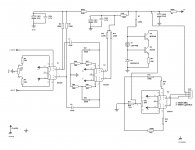
Here is a Schematic that's more complete. The inout is a 1:10 Mic input XFMR. Actually David Garen at Cinemag sent me on this exploration of current sinks. It's been a bit of a rabbit hole.
BTW, the original circuit calls for 11V at the Cathodes. I am also planning on trying this with a 12BH7 and ECC88 at 24-30 mA shared current.
Here is a Schematic that's more complete. The inout is a 1:10 Mic input XFMR. Actually David Garen at Cinemag sent me on this exploration of current sinks. It's been a bit of a rabbit hole.
Attachments
Last edited:
Hi RE is good because the impedance seen at the collector of the bottom transistor is approx.. RE x Beta (hfe) of that bottom transistor. So as well as high RE you want a "C" version of the bottom transistor. "A" like BC547A means hfe of 0-100, B means 100-300, and C means >300. I might not have thoe values exactly correct but you get the drift.
The problem here is to get a high RE you have put a high base voltage on that bottom transistor. More hfe and higher RE is good and the impedance (CCS goodness) is then limited by Early Effect. Early is the guys name who described this effect, nothing to do with "stuff" happening before you expect it to. The cascoded upper transistor removes that limitation.
You can not have a base voltage on the bottom transistor of 12V and then hope to get a bias voltage at the 12AU7 cathodes of 11V. That is what I mean by the CCS has run out of compliance voltage.
With the existing circuit values the CCS is acting more like a Zener diode and fixing the cathode voltage not the cathode current coz the transistors have run out of operating voltage.
The suggested fix will address that but as you have noted the CCS performance is compromised a bit by the lowish RE that is then required.
This is typical Electronics design where one of the maxims is "You can't do just one thing". Usually changing one thing leads to domino effects.
6.2V was from ASSUMING a +10v bias at the cathodes and subtracting the estimated modified CCS operating (compliance) voltage of 3.8V.
You also do not need an MJE340 as the top transistor. Any small signal transistor will do. make it the same as the bottom one. The beefier MJE340 will give some protection from tube shorts because of it voltage rating but it trades hfe to get that higher power/voltage rating.
Cheers,
Ian
Last edited:
Hi RE is good because the impedance seen at the collector of the bottom transistor is approx.. RE x Beta (hfe) of that bottom transistor. So as well as high RE you want a "C" version of the bottom transistor. "A" like BC547A means hfe of 0-100, B means 100-300, and C means >300. I might not have thoe values exactly correct but you get the drift.
The problem here is to get a high RE you have put a high base voltage on that bottom transistor. More hfe and higher RE is good and the impedance (CCS goodness) is then limited by Early Effect. Early is the guys name who described this effect, nothing to do with "stuff" happening before you expect it to. The cascoded upper transistor removes that limitation.
You can not have a base voltage on the bottom transistor of 12V and then hope to get a bias voltage at the 12AU7 cathodes of 11V. That is what I mean by the CCS has run out of compliance voltage.
With the existing circuit values the CCS is acting more like a Zener diode and fixing the cathode voltage not the cathode current coz the transistors have run out of operating voltage.
The suggested fix will address that but as you have noted the CCS performance is compromised a bit by the lowish RE that is then required.
This is typical Electronics design where one of the maxims is "You can't do just one thing". Usually changing one thing leads to domino effects.
Cheers,
Ian
Thanks for being so helpful Ian. The phrase no free lunch applies so much with electronics. Yes after reading your post a couple times I then realized where you got 6.2 from. But how much free lunch is given after the 3.8V is used? Or how much compliance is needed? Say for understandings sake I was to use a 2.5 volt or 6.2 V reference on the bottom?
And also what would happen trying to CCS a 12ax7 biased at 1.5V? With 3.8V being used up already...
And also what would happen trying to CCS a 12ax7 biased at 1.5V? With 3.8V being used up already...
The Merlin b reference is a combo of this:
The Valve Wizard
And his books. And from the bottom page of the link it appears that 1.8V from 3 diodes is already “used up” but he’s claiming the bias is set at 1.5V. Hmm
The Valve Wizard
And his books. And from the bottom page of the link it appears that 1.8V from 3 diodes is already “used up” but he’s claiming the bias is set at 1.5V. Hmm
Woo Whooo!!!! Ian you Rock! 12h7 output CCS Up and running at 28 mA with Re=41R, adjustable and correct Vk. I paralleled a 100R pot with a 68R for Re. Then 2 ZTX690b's. One ZTX came out at 700 Hfe and I'm guessing the other one is close giving me 20 Meg Z.
The one thing about the CCS is that they pull more current from biasing the current supply cascode.
The current circuit is a 2 stage version of the original differential preamp with the input tube biased at 1 mA per side at 1.5V, with 100K Ra and 1.25K Rk. which is probably the weakest part. but I am pretty happy with the sound of the CCS. More dynamic and lower THD by .05%
Here's a pic. The CCS PCB I made fits 600 mil resistor spacing via 90 degree 100 mil header pins. I still have a pot between the CCS and the tubes to protect the transformer from magnetization.
Last edited:
CCS on Push pull output 12h7
Ok I got dual CCS's on the output to protect the transformer. So far any tube I've dropped in has has under a 20 mV difference across Anode. But when I wen from a shared CCS to the dual config the bass seemed to suffer a bit. It still shows a pretty flat reading on the AP but with the mic it seemed to decrease.
Merlin talks about bypassing with a 18KF cap, but says you can get decent results with a few thousand uF, in his HIFI tube book CCS section. The question mark cap is what I am wondering if it's useful and will get bass response better. Just across voltage references.
I drew I tubecad's coupling circuit with the 1 M resistor which I tried but didn't notice much. I also tried np caps between cathodes up to 33 uF not much either.
Also wondering if the 30V zener on the right would do any good.
An externally hosted image should be here but it was not working when we last tested it.
- Status
- This old topic is closed. If you want to reopen this topic, contact a moderator using the "Report Post" button.
- Home
- Live Sound
- Instruments and Amps
- CCS on 12AU7 Push-Pull