M Pro Audio Series 611815 15watt clone monoprice 15watt
I got this amp, its a Monoprice 15 watt 112 tube amp combo thats suppose to be modeled after the Laney Cub12R. There is a schematic online for the guts of this head somewhere if someone would kindly have a look.
So the story of this amp is, it was plugged in and running when an old vintage electric heater was plugged into the same socket outlet and turned on then something in the amp popped.
From what I was told after the amp popped from the electric heater event, these three areas were attempted to be repaired:
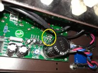
#1 The amps original R2 and R12 had stock units in it, but they looked a bit cooked and bubbled and were replaced with 1/4 watt carbon film standard 1k resistors.
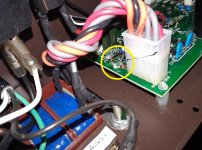
#2 The F1 PTC6.0 30V 6A JK30-600 resettable fuse. That component was replaced with a jump wire, in an attempt to get the amp to turn on.
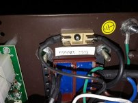
#3 With the amp like this, it kept popping the T500mA 250v glass fuse every time it was turned on. It never came on sense then.
Im new to tube amp repair. I know its very dangerous to work on them, and to stay away from metal parts when its plugged in and to avoid the filter caps, and always one hand in my pocket with shoes and socks on. And to unplug amp & bleed the filter caps and check with a multimeter to make sure they are empty BEFORE I attempt to work on a tube amp.
My question is, mainly about the two resistors. From the homework I did, the R2 and R12 are suppose to be replaced with a pair of flameproof 1k 1/2 watt fusible resistors. Is this right?
I figured thats what value I need for the pair because of the schematic and I measured the original resistors size and they were 3mm tall and 9.5mm long. I currently have the pair of R2 and R12 resistors removed from the board, the T500mA 250v fuse socket empty, and the F1 PTC6.0 30V 6A JK30-600 resettable fuse spot removed also.
These three areas are ready for the new parts. Im wondering if R2 and R12 are really flameproof 1k half watt fusible resistors. Is there any more measurements I need to know about these resistors in order to purchase the correct replacement parts?
And also after I install these parts, what if the amp still does not turn on?
I got this amp, its a Monoprice 15 watt 112 tube amp combo thats suppose to be modeled after the Laney Cub12R. There is a schematic online for the guts of this head somewhere if someone would kindly have a look.
So the story of this amp is, it was plugged in and running when an old vintage electric heater was plugged into the same socket outlet and turned on then something in the amp popped.
From what I was told after the amp popped from the electric heater event, these three areas were attempted to be repaired:
#1 The amps original R2 and R12 had stock units in it, but they looked a bit cooked and bubbled and were replaced with 1/4 watt carbon film standard 1k resistors.
#2 The F1 PTC6.0 30V 6A JK30-600 resettable fuse. That component was replaced with a jump wire, in an attempt to get the amp to turn on.
#3 With the amp like this, it kept popping the T500mA 250v glass fuse every time it was turned on. It never came on sense then.
Im new to tube amp repair. I know its very dangerous to work on them, and to stay away from metal parts when its plugged in and to avoid the filter caps, and always one hand in my pocket with shoes and socks on. And to unplug amp & bleed the filter caps and check with a multimeter to make sure they are empty BEFORE I attempt to work on a tube amp.
My question is, mainly about the two resistors. From the homework I did, the R2 and R12 are suppose to be replaced with a pair of flameproof 1k 1/2 watt fusible resistors. Is this right?
I figured thats what value I need for the pair because of the schematic and I measured the original resistors size and they were 3mm tall and 9.5mm long. I currently have the pair of R2 and R12 resistors removed from the board, the T500mA 250v fuse socket empty, and the F1 PTC6.0 30V 6A JK30-600 resettable fuse spot removed also.
These three areas are ready for the new parts. Im wondering if R2 and R12 are really flameproof 1k half watt fusible resistors. Is there any more measurements I need to know about these resistors in order to purchase the correct replacement parts?
And also after I install these parts, what if the amp still does not turn on?
Attachments
Last edited:
Here is a link to your possible schematic.
http://www.epiphonetalk.com/media/schema-final.736/full?d=1479744786
If it is, your problems are likely more than burned fuse and R2//R12. The first fuse is a low voltage fuse which also supply the negative bias to the output tubes. When that blow, the output stage current go crazy. The output tubes, output transformer and R2/R12 will over stress. Hopefully R2+R12 go first before the other burns up. If that is the case, replacing them will fix that problem. However, the root cause is what caused the low voltage fuse to burn in the first place. You need to find out what went wrong there first. Good luck.
Here is a link to your possible schematic.
http://www.epiphonetalk.com/media/schema-final.736/full?d=1479744786
If it is, your problems are likely more than burned fuse and R2//R12. The first fuse is a low voltage fuse which also supply the negative bias to the output tubes. When that blow, the output stage current go crazy. The output tubes, output transformer and R2/R12 will over stress. Hopefully R2+R12 go first before the other burns up. If that is the case, replacing them will fix that problem. However, the root cause is what caused the low voltage fuse to burn in the first place. You need to find out what went wrong there first. Good luck.
Thank you so much for your reply. The amp was working fine, until that electric heater was plugged in and turned on in the same electrical outlet while the amp was being used.
The person I got the amp from did say he took the amp to an amp tech and the amp tech said the output transformers were ok.
The amp was working fine and totally stock inside that I know of, before the short hapend.
The first fuse is a low voltage fuse which also supply the negative bias to the output tubes.
By first fuse do you mean the F1 PTC6.0? Pictured in the schematic? That fuse actually did not burn out or short out, it was just replaced with a jump wire from an experiment lol. And im sure it was not a very wise experiment.
Last edited:
And im sure it was not a very wise experiment.
Agreed. Build/borrow a "light bulb tester" wfch puts a mains bulb in series with your incoming mains. fire up your favourite search engine and find instructions on debugging a bad valve amp (Rob Robinette is also worth reading).
Basic steps
a) unplug from wall; check that ALL the B+ capacitors are drained.
b) take out all the tubes and all fuses except the mains incomer
c) crack out your multimeter and check as many of the components as you can, including the OPT. Check PT windings (especially for shorts to ground)
d) if you can disconnect the power transformer from the rectifier easily, do it.
e) put a low wattage (40W) bulb in the tester; hook up mains; stand clear and turn on from the wall. If it lights up your problem is in the mains /power transformer. If not, check some voltages. Optional: put a decent load on the heater supply and see if the PT can survive it.
f) repeat (e) with increased number of valves, starting with the rectifier and moving towards the output stage. Your B+ values will be a bit high in the beginning (due to a lack of load) but for most small modern amps this should not cause a problem in and of itself. If the bulb lights up, something's amiss.
That's basically it, there's a multitude of little variations. And the usual solid state tips work (replace a blowing fuse with a suitable resistor) still apply but as the amps get bigger & the B+ supply hairer, the need for dummy loads and other tweeks increases. But I'll leave you and your search engine alone at this point.
Last edited:
Google schematic Laney Cub12R, gives you service manual as first hit. Surprised you never thought to supply the link. First pull all the tubes turn it on. Should be no current draw. You can check the transformer voltages and dc voltages. If something blows you don't have to look too far to find it. I don't buy the heater thing, should not matter. Strange the tech found the transformers are good but did not manage to isolate what might be the problem.
Just a noob question, but I noticed the R2 & R12 two resistors run from ground directly to pin 9 of the V5 EL84 power tube socket. Thats the screen grid pin am I right? And does that in fact make the pair of resistors the screen resistors?
And being the screen resistors were replaced with 1/4 watt standard metal film ones, and my estimate that the board calls for 1/2 watt flameproof 1k fusible resistors,
If power tubes were plugged into those sockets when the amp was turned on then shorted within a few seconds, then turned off with the wrong resistors. Is it safe to say I should get a new pair of matched power tubes?
The screen resistors go to the high voltage supply. Look at the schematic, it says 300V on one side of the resistors and 290V on the other side which goes to the screens.
What was shorted for a few seconds?The tubes, the power supply, the resistors?
Does any of the above tell me to get a new pair of tubes? No, I have no idea what is going on without more information.
If power tubes were plugged into those sockets when the amp was turned on then shorted within a few seconds, then turned off with the wrong resistors. Is it safe to say I should get a new pair of matched power tubes?
What was shorted for a few seconds?The tubes, the power supply, the resistors?
Does any of the above tell me to get a new pair of tubes? No, I have no idea what is going on without more information.
The screen resistors go to the high voltage supply. Look at the schematic, it says 300V on one side of the resistors and 290V on the other side which goes to the screens.
What was shorted for a few seconds?The tubes, the power supply, the resistors?
Does any of the above tell me to get a new pair of tubes? No, I have no idea what is going on without more information.
Thanks for the reply. The amp still sits as it did as described in the first post of this thread. Its still waiting for the new parts. I am still studying up on the repairs and I noticed the R2 & R12 went to pin 9 on the circuit board V5 power tube socket.
And I was just confirming that the two resistors I had in question were in fact the screen resistors. Thats all. And I was wondering what kinda damage could it do with the wrong screen resistors installed, as some were in this poor lil guy.
Also I am thinking that the replacement screen resistors should be at least 350v units huh. Anyone know an easy place to find these guys as replacements? I am going to hunt high n low on google.
Last edited:
Can and should I run a pair of 500v 1k 1 watt fusible resistors for the screen resistors R2 & R12?
Reason I ask is the resistors I ordered were only rated at 250v. And the pair listed on the schematic are surrounded by 290 & 300 volts.
and the stock resistors measured out to be 1/2 a watt.
Reason I ask is the resistors I ordered were only rated at 250v. And the pair listed on the schematic are surrounded by 290 & 300 volts.
and the stock resistors measured out to be 1/2 a watt.
...I ordered were only rated at 250v. And the pair listed on the schematic are surrounded by 290 & 300 volts.
...and the stock resistors measured out to be 1/2 a watt.
Yes you have 300V one end and 290V on the other end. The resistor FEELS just ten Volts! Bird on a wire. It is fine until it puts its other foot on ground.
The plan clearly says 1W FP. Were they really 1/2W from the factory? Then you have a case where a prototype was Safety Tested with /!\ parts which would not start a fire..... then in production they changed to cheaper parts, safety be danged! This happens. This is not a Good Sign.
These should be sturdy but not too sturdy resistors. The normal strain is small, well under 1W. But a common failure is power tube G2 short to Cathode. "Infinite" current wants to flow. I have seen a power transformer burn-up from this. With some resistance and ample but not excessive dissipation rating (and preferably no flame), a shorted tube is a minor repair instead of a major rebuild or a panicked crowd.
Last edited:
Yes you have 300V one end and 290V on the other end. The resistor FEELS just ten Volts! Bird on a wire. It is fine until it puts its other foot on ground.
The plan clearly says 1W FP. Were they really 1/2W from the factory? Then you have a case where a prototype was Safety Tested with /!\ parts which would not start a fire..... then in production they changed to cheaper parts, safety be danged! This happens. This is not a Good Sign.
These should be sturdy but not too sturdy resistors. The normal strain is small, well under 1W. But a common failure is power tube G2 short to Cathode. "Infinite" current wants to flow. I have seen a power transformer burn-up from this. With some resistance and ample but not excessive dissipation rating (and preferably no flame), a shorted tube is a minor repair instead of a major rebuild or a panicked crowd.
Where on that schematic does it say 1w FP? What I am seeing is 1K FP. On R2 & R12?
Thanks for your replies. I am just wondering if a pair of 1 watt 1k fusible flameproof 500v resistors is a better idea as replacements instead of the
half watt 1k 250v fusible flameproof resistors I was thinking of using.
Let's start again. PRR has said that you have 300V on one side of the resistor and 290V on the other. So there is only 10V across the resistor. (actually I said that also) You seem to be hung up on the voltage rating. If there is 1000V at one end of the resistor and 990V at the other end there is still only 10V across the resistor.
That is one hint that I am concerned about troubleshooting the amp at a distance. The other thing that worried me was your saying the resistor goes from the screen to ground. I thought either you are not reading the schematic or do not comprehend how things are hooked up.
As far as the resistor you selected, the Digi-Key web page says that the resistors are out of stock and there is a 14 week lead time. That is the normal wait time but it seems that there is a part shortage going on and it may be longer. It also says that the standard package is 100, so you will be paying $3.0795 per unit and a total price of $307.95. The good news is that Digi-key will probably offer free shipping if you order this part. Probably could get a new amp for less than $307.95.
This one may be a better selection at $0.83 a piece in quantities of one. Vishay Dale CPF11K0000FKEE6
CPF11K0000FKEE6 Vishay Dale | Resistors | DigiKey
They will probably ding you for shipping though. It would be good to know what the health of the amp is otherwise, if you are going to do multiple purchases from them shipping charges are going to hurt. Oh wait can you see, (never mind, my mind has a different sense of humour) these prices are in CND, your price may be less.
Or if you are looking for 1/2W there is the PPC1.0KBCT-ND.
NFR25H0001001JR500 Vishay BC Components | Resistors | DigiKey
I don't know if they want the resistor to burn up fast or not, my money would be on the 1W though. Since you have an amp that seems to like eating them I might get more than two.
Let's start again. PRR has said that you have 300V on one side of the resistor and 290V on the other. So there is only 10V across the resistor. (actually I said that also) You seem to be hung up on the voltage rating. If there is 1000V at one end of the resistor and 990V at the other end there is still only 10V across the resistor.
That is one hint that I am concerned about troubleshooting the amp at a distance. The other thing that worried me was your saying the resistor goes from the screen to ground. I thought either you are not reading the schematic or do not comprehend how things are hooked up.
I understand the volts of the R2 & R12 now lol, thanks for clearing that up for me.
And I did misslook at my board, the first two leads from R2 & R12 go to the pin 9 and the other two leads go to a pin of the largest filter cap.
- Status
- This old topic is closed. If you want to reopen this topic, contact a moderator using the "Report Post" button.
- Home
- Live Sound
- Instruments and Amps
- Monoprice 15 watt tube amp problems