If the circuit has been optimized for guitar, it will sound really wimpy with a bass. The lowest guitar frequency is around 80Hz, whereas a five string bass can dip to 35Hz, give or take.
This is subjective stuff, so what works for you may not work for the next guy, so be prepared for a bit of experimentation. The first thing to do is to double the value of all the caps in the signal path (meaning the coupling caps in between the gain stages and the emitter bypass caps inside each gain stage). Doubling values tends to drop the frequency response in half. You're looking at 40Hz now, and right around the low E of a bass guitar.
There's no magic to doubling, however. Try even larger values if you like, and if they don't work, chalk it up to The Big Experiment and take 'em out. Make some bigger, some smaller. Stop when it sounds good to you.
The term for this experiment is "Re-Voicing" the circuit to suit your tastes. Your friends will be impressed.")
Dave
This is subjective stuff, so what works for you may not work for the next guy, so be prepared for a bit of experimentation. The first thing to do is to double the value of all the caps in the signal path (meaning the coupling caps in between the gain stages and the emitter bypass caps inside each gain stage). Doubling values tends to drop the frequency response in half. You're looking at 40Hz now, and right around the low E of a bass guitar.
There's no magic to doubling, however. Try even larger values if you like, and if they don't work, chalk it up to The Big Experiment and take 'em out. Make some bigger, some smaller. Stop when it sounds good to you.
The term for this experiment is "Re-Voicing" the circuit to suit your tastes. Your friends will be impressed.
Dave
The "simple change" is to double the size of all caps.
But musically, bass is NOT a half-pitch guitar, sets differently in the music, so simple scaling is not always a happy result.
Also some basses have much higher output than most guitars, which may lead to nasty over-overdrive.
Why "this" guitar overdrive? Aren't there plans for bass overdrives floating around?
used to build and experiment with stripboards, bread boards and vero, work is just taking up too much time so bought a couple of pre etched pcbs. plan to use one as is for guitar and try adjust the other for bass to give to someone in the north island. unfortunately i already sent them a bass amp so only have a PA to test through.
Hi,
I chose this one because I knew I would need some advice and it looks quite simple so i would have to hopefully not ask to many questions to gain some of the knowledge to help me learn to designing.
if the drive got nasty (i think because it has no clipping diodes) would it be better to lower the value of resistors from emitter to ground or lower the resistors value (R7,R11,R16) to lower the gain?
thanks will check it nowIf you go to Brian Wampler’s YouTube channel he has ideas of how to modify various guitar OD pedals for bass.
thanks, I was wanting to do something like that would i need to add a buffer at the start and some kind of balance knob at the output?My recommendation would be to not modify it at all, but build a blender loop for it. A wet/dry blend is what the 4th knob on a commercial bass overdrive typically is.
thanks I will do that and socket the caps until i have it right, i think i have seen 1uf used on stereos for coupling and they have to be able to allow bass through. i have done guitar before and only gone up as 68nf i think.If the circuit has been optimized for guitar, it will sound really wimpy with a bass. The lowest guitar frequency is around 80Hz, whereas a five string bass can dip to 35Hz, give or take.
This is subjective stuff, so what works for you may not work for the next guy, so be prepared for a bit of experimentation. The first thing to do is to double the value of all the caps in the signal path (meaning the coupling caps in between the gain stages and the emitter bypass caps inside each gain stage). Doubling values tends to drop the frequency response in half. You're looking at 40Hz now, and right around the low E of a bass guitar.
There's no magic to doubling, however. Try even larger values if you like, and if they don't work, chalk it up to The Big Experiment and take 'em out. Make some bigger, some smaller. Stop when it sounds good to you.
The term for this experiment is "Re-Voicing" the circuit to suit your tastes. Your friends will be impressed.
Dave
Also some basses have much higher output than most guitars, which may lead to nasty over-overdrive.
Why "this" guitar overdrive? Aren't there plans for bass overdrives floating around?
Hi,
I chose this one because I knew I would need some advice and it looks quite simple so i would have to hopefully not ask to many questions to gain some of the knowledge to help me learn to designing.
if the drive got nasty (i think because it has no clipping diodes) would it be better to lower the value of resistors from emitter to ground or lower the resistors value (R7,R11,R16) to lower the gain?
I've seen most of the coupling are 100nf except one 10nf,does anyone think that could be a mistake in the schematic? would having the way smaller coupling cap defeat the purpose of having the rest larger or do people use larger and smaller value coupling at different stages for a reasons?
Wondering should I go larger on the tone capacitor C10 to ground and does R19 help decide how strong the affect of C10 has signal? i read this configuration is a treble cut.
I think i have seen the 470p / 470k parallel used with op circuits. does these values effect tone or it just to stop oscillations? should the 470p be ceramic type in this position?
Last edited:
Yes, yes, and yes. Might be a mistake, might be intentional, part of the "voicing" of the pedal.I've seen most of the coupling are 100nf except one 10nf,does anyone think that could be a mistake in the schematic? would having the way smaller coupling cap defeat the purpose of having the rest larger or do people use larger and smaller value coupling at different stages for a reasons?
You have to look at both the capacitor value, and the value of the resistor it feeds; a smaller capacitor will let through just as much deep bass if it's feeding a larger resistor.
In this circuit, it's hard to tell what the (input) resistance of each stage is. That's why people are telling you to just double all the capacitors as a starting point, which will halve all the bass roll-off corner frequencies.
For an audio circuit, a capacitor is a capacitor. Use whatever type you like, there is no difference, as long as its 470pF. Ceramic, polycarbonate, polystyrene, whatever.Should the 470p be ceramic type in this position?
(If you were building a circuit to operate at microwave frequencies, it would be a different story. But you're not.)
By the way, input impedance of this pedal is probably low enough to cause "tone suck". That is intentional and part of the distorted tone for some guitar distortion pedals. I don't know how well it will translate to a bass guitar.
-Gnobuddy
thanks, I was wanting to do something like that would i need to add a buffer at the start and some kind of balance knob at the output?
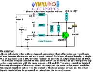
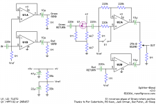
I would build it with 3 buffers, a simplified version of this:
Splitter-Blend
A single TL074 would be all you need.
Here's a good article that explains the role of the roll off caps, albeit this is for a tube screamer: Fat Mod for the TS-808
Again, I have to say I recommend against what you are trying to do, putting a bass' full range through a distortion box will produce a muddy, unusable tone.
Have a look at the Darkglass B3K for inspiration now that it's finally been cloned:
Pepers' Pedals: A brief guide into tracing out a PCB to convert to schematic. b3k Clone
The 2:1 capacitance increasing trick does not work here, to begin with because even a proper Guitar Distortion pedal does NOT reach Guitar lower frequencies, by any means.
Low frequencies are **strongly** cut to avoid farting, period, and sadly Bass Guitar frequencies *all* are within the farting range, cutting them off simply makes the Bass Guitar disappear, period.
Or if you lave them, it´s Fart City.
FWIW these are the bass cut frequencies in some popular, iconic pedals and amplifiers which are known for their excellent overdrive:
* MXR Dist+: .047uF+4k7: 720 Hz
* Tube Screamer: .047uF+4k7: 720 Hz we seem to have a pattern here
* Marshall Plexi, bright channel: .0022uF+470k: 154 Hz
* VOX AC30: 500pF+500k: 637Hz
and so on and on and on.
The point being that even doubling capacitors (halving cutoff frequency) we are still very far from Bass Guitar frequencies.
Do you know Chris Squire's signature, slightly overdriven, but still distinctive bass guitar sound? As far as I've read some time ago, he used the Rick'O'Sound jack of his Rickenbacker 4001S, feeding the neck pickup's signal through an almost full range, clean sounding tube amplifier, and the bridge PU through another tube amp that had a rather high LF roll off and with it's volume set to crunch some bit. Translated to a stomp box, you'll need an x-over network next to the input with a clean full range channel and an overdriven channel just for the higher tones, and eventually a mixer stage to combine both.
Best regards!
Best regards!
That's pretty much exactly what Seymour Duncan says as well: https://www.seymourduncan.com/blog/the-tone-garage/unlocking-the-secrets-of-bass-distortionTranslated to a stomp box, you'll need an x-over network next to the input with a clean full range channel and an overdriven channel just for the higher tones, and eventually a mixer stage to combine both.
The best bass player I've ever met in person also used to use a microphone placed near the fretboard of his bass to pick up those slight fretting and fingering noises, and mix them into his overall sound. He says they add realism and interest to the bass guitar sound.
-Gnobuddy
hello , i have been working on this project and am having some problems
i have researched and studied bass amps and band pass for the cap values for a bass version but am working on getting a guitar version working first
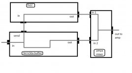
my problem is with sorting a mixer/ blend for the clean sound.i am getting alot of oscillation that varies pitch when i turn any of the knobs. making it almost unusable unless i drop the voltage right down. then i can just avoid the oscillating area on the pots. this leave not much headroom though because i only have 9v battery to start with. ( btw i dont have a scope)
i have studied what i can find for causes and all my leads are short and signal lead are shielded and i have tried a 1meg vr trim pot to varied the impeadance to overdrive stage and still have problem.
i wonder i i have to remove mixer pot and build the yamaha channel audio mixer in other schematic at the end of the circuits?
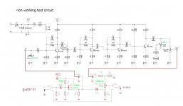
could someone please take a look and maybe tell why i have this problem please. the changes to original schematics are in green.
i have researched and studied bass amps and band pass for the cap values for a bass version but am working on getting a guitar version working first
my problem is with sorting a mixer/ blend for the clean sound.i am getting alot of oscillation that varies pitch when i turn any of the knobs. making it almost unusable unless i drop the voltage right down. then i can just avoid the oscillating area on the pots. this leave not much headroom though because i only have 9v battery to start with. ( btw i dont have a scope)
i have studied what i can find for causes and all my leads are short and signal lead are shielded and i have tried a 1meg vr trim pot to varied the impeadance to overdrive stage and still have problem.
i wonder i i have to remove mixer pot and build the yamaha channel audio mixer in other schematic at the end of the circuits?
could someone please take a look and maybe tell why i have this problem please. the changes to original schematics are in green.
Attachments
Last edited:
hello, yes that is a very good idea, i have a same kind of sound with this so far when i try bass through it. the clean bass signal is full range with the 10uf pre stage then the over drive effects the mid /high tone too, it is very good sound. if i play electric guitar in and mix od/clean right and then drop the voltage down it compresses and sound like an acoustic guitar, boom in deep notes, light sounding highs.Do you know Chris Squire's signature, slightly overdriven, but still distinctive bass guitar sound? As far as I've read some time ago, he used the Rick'O'Sound jack of his Rickenbacker 4001S, feeding the neck pickup's signal through an almost full range, clean sounding tube amplifier, and the bridge PU through another tube amp that had a rather high LF roll off and with it's volume set to crunch some bit. Translated to a stomp box, you'll need an x-over network next to the input with a clean full range channel and an overdriven channel just for the higher tones, and eventually a mixer stage to combine both.
the drive gives the subtle string buzz the acoustic has when you strum hard, sounds like acoustic simulator at certain voltage and settings. should record demo and link the sound. just need to solve the oscillation problems so it has a usable range
the drive circuit on its own is quite harsh and nothing special sounding, better with the pre circuit in front and mixed with clean.
Last edited:
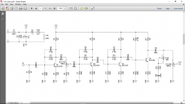
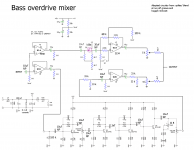
The circuit on the left has four high-gain transistor stages, and your schematic shows all four operating off the same Vcc, without even a decoupling cap to ground. If the actual circuit is built exactly like the schematic, it is a recipe for oscillation problems because of unwanted signal coupling through the Vcc supply line.i have studied what i can find for causes and all my leads are short and signal lead are shielded
At a minimum, try a 0.1uF ceramic cap and a 100 uF electrolytic cap (in parallel), both connected from Vcc to ground, as close as possible to the four transistors in the fuzz circuit.
If the mixer is on a separate PCB, do the same thing for the mixer as well.
You may need to take additional steps beyond this, but try the simple things first - maybe that will solve the problem for you.
There are mistakes in the mixer schematic. First, the 100k resistor between collector and base of the 2N3904 will completely ruin the circuit biasing - add a 0.1uF cap in series with it, so that DC current cannot flow from collector to base.
Second, the 1.2Meg resistor is too big by a factor of about 300%. Perhaps this circuit was originally designed for a higher gain transistor, and the person who substituted a 3904 didn't understand how that would affect bias? At any rate, remove and throw away the 1.2 Meg resistor, and replace it with a 390k or 470k resistor.
Finally, I suggest putting a small capacitor between collector and base of the 2N3904, to control bandwidth. You can use 100pF, 82pF, or 47 pF here.
The mixer should come after the fuzz, not before. Do you have it before the fuzz now?i wonder i i have to remove mixer pot and build the ymya channel audio mixer in other schematic at the end of the circuits?
-Gnobuddy
hi Gnobuddy, thanks for all the advice i will try what you have suggested. so far i have only built the block diagram on the left.The mixer should come after the fuzz, not before. Do you have it before the fuzz now?
by saying "removing the the mixer pot" I ment to say "should i remove the balance pot and build the ymya mixer"
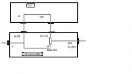
I thought the passive balance control may have been causing the oscillations so was going to change the layout to the block diagram picture on the right but may not need to now.
i tried this simple order like normal effect chain just after i posted last post .....
guitar to ____k30a jfet buffer _____ to fuzz ____to amp
..... and still had problem so figured it wasnt the balance pot part of the circuit creating the problem and thought maybe the fuzz was only designed to handle a a passive guitar signal.
will try the sugestions and post the results
Attachments
Hi,At a minimum, try a 0.1uF ceramic cap and a 100 uF electrolytic cap (in parallel), both connected from Vcc to ground, as close as possible to the four transistors in the fuzz circuit.
I tried this suggestion and when running
----guitar to ____k30a jfet buffer _____ to fuzz ____to amp ---
and only got oscillations when volume gain pots were at very high settings.
when running
___guitar to ____k30a jfet buffer to ____ fuzz ____ Balance pot______to amp
.............................................\____to pot_____/
I got oscillations at mid range volume gain settings.
Am thinking to replace k30a jfet buffer with the op circuit below and maybe try find a lower gain sub transistor for the first bc549 in the fuzz circuit.
I think it would be good to build op circuit below but with a higher voltage than 9v using +/- power rails and just use a 9 vreg to drop the voltage for the fuzz circuit.
but am not sure how the higher Voltage would effect operating capability of Q1 in the circuit below or if the rest of the design would operate with a higher voltage.
Attachments
Last edited:
- Status
- This old topic is closed. If you want to reopen this topic, contact a moderator using the "Report Post" button.
- Home
- Live Sound
- Instruments and Amps
- converting a guitar overdrive to bass overdrive