How did you calculate the ~320mA?Looks near-right to me. On steady Sine the DC current would be ~~320mA. (Remember two current paths working alternately through a Totem Pole.) Even heavy guitar is not as severe, over a full set, as a steady Sine. Apparently they like a 50% fudge factor between test and playing
A fellow by the name of Roly Roper on the Aussie Guitar Gearheads forum found a Microcube in the dumpster, and tried it out with his electronic keyboard. He noticed the very drastic bass roll off, then went looking for a measured frequency response.Is this an aural observation, or have you measured it?
I don't recall if he measured it himself, or found a measurement someone had made - either way, he posted a measured frequency response, and it had the drastically attenuated bass response I mentioned. This was measured across the speaker terminals I believe - it was smooth and uniform, and didn't have the jaggies you always see when you measure the acoustic output of a speaker with a microphone.
It's been a couple of years since I saw Roly's post, and I can't remember if the measured response was 3 dB down at 500 Hz, or 1 kHz. (I think - but am not sure - that it was actually 1 kHz. That shocked me at the time.)
This was definitely electronic, though I don't know at which stage in the chain. My guess is that you're probably right about it being in the power amp.I wonder if they do it electronically in the power stage, or if it is just an artifact of the crummy little 5" speaker?
That could be an advantage for battery operation.My application (C6 lap steel) requires less bass, as the lower strings are tuned ~ a fifth above a regular guitar.
In a mix with bass and drums, I find I don't miss the bottom octave of electric guitar (high-pass at around 160 Hz). Sometimes the guitar "sits in the mix" better if I high-pass it as high as 300 Hz, though that sounds quite thin on its own. But it gets along better with the bass guitar, drums, and/or left hand of the keyboard player.
If you're going to be playing along with drums and or bass, you might get away with much less deep bass from your lap steel than you would think.
-Gnobuddy
If it is a normal push-pull output (and not two amps with the speaker hanging between them in bridge mode), I think we may have been overestimating the (already very limited) capabilities of the microcube.How did you calculate the ~320mA?
You are always going to lose a volt or more to output device saturation at each end of the voltage swing, so with a 6 volt supply, it's very unlikely you will ever see a clean sinewave bigger than 4 volts peak to peak across the 4 ohm load. More likely the max is closer to 3 volts peak to peak.
Being generous and assuming 4 volts peak to peak across 4 ohms, we have a peak voltage of only 2 volts.
That means peak speaker current = 2V/4 ohm = 0.5 amps
RMS power to speaker = peak power/2 = 1 watt.
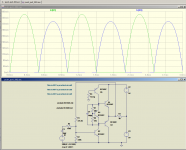
For fun, I threw together a simple push-pull amp in LTSpice; resistance values are tweaked to bias it perfectly in the simulator, but this is not a practical circuit for real-world use where parameter spreads and temperature variations have to be dealt with.
In the sim, as I expected, even with no battery voltage droop, the output starts to clip before you get a full 4 volts peak-to peak to the speaker. Peak speaker current never gets to 500 mA, but tops out at around 380 mA.
The green half-sine curves are the current drawn by one of the two output transistors. The blue ones are the current drawn by the other output transistor. They are slightly unequal because the amp is crude and there is some distortion at full output.
While those peaks get to 380 mA, there is a lot of empty space between the peaks; the average value for a full-wave-rectified sinewave like this is the peak value multiplied by 2, and then divided by pi (3.1416).
In our case, while peak currents are 380 mA, the average current from the battery will be less than two-thirds of that, or around 240 mA. And that's at maximum clean output.
So what we're looking at is a 1 watt amp whose output stage probably draws about a quarter of an amp at full clean output.
I have no idea how much current all the digital stuff in the preamp draws. Considering how puny the output stage is, the preamp might draw a significant proportion of the total power.
It is possible the microcube actually uses a pair of output amps in bridge mode, in which case the output power might approach a thundering 4 watts RMS (clean), rather than the 1 watt I estimated from a single amp.
-Gnobuddy
Attachments
I shouldn't have posted at 1 AM - I made a couple of math errors.
2 volts peak, 0.5 amp peak. Peak power is then 2 x 0.5, or 1 watt.
RMS power is half of the peak power, so only 0.5 watts (not 1 watt, as I posted last night.)
I also miscalculated the average current. The current waveform through each output transistor does look like a half-wave-rectified sine, as shown in the LTSpice sims. But each transistor only pulls that current waveform from 3 volts (half the battery)...the net effect being that average current draw from the 6V battery will be around 120 mA, not 240 mA.
Okay, so roughly 1/8 amp average current from the battery; that's about 3/4 watt drawn from the 6 V battery (i.e. 1/8 x 6 ). And half a watt of that 3/4 watts is delivered to the speaker.
Only half a watt RMS? Hmm. (If the microcube really does deliver 2 W to the speaker, rather than the 1/2 watt I estimated above, then we know it does indeed have a bridge-mode power amp, which delivers four times the power you'd get from an unbridged output.)
-Gnobuddy
...You are always going to lose a volt or more to output device saturation at each end of the voltage swing, so with a 6 volt supply ....
It is stated up-thread we got 6 AA cells. This will be 9V, not 6V, when fresh. (And obviously the specs are given with nice fresh batteries; they can't say how long/hard you will beat on them, but everybody knows batteries fade.)
And there are low-drop chips in this size range. I rounded-down from 9V to 8V because I know 8Vpp is 2.828V RMS, 1W in 8r or 2W in 4r. Which seems to echo the published specs.
Current consumption can be estimated many ways.
I once figured a totem-pole feeding 8r acts-like 48r load on the power supply. So 4r load acts-like 24r. This assumes voltage-loss is small. Well, just assume 8V and we have 8V/24r, easy math, 0.33A.
Class B gets to 78% efficiency. Any decent AB transistor amp approaches 75%. So a 2W output needs 2.66W of DC power. 2.66W/8V is about 0.33A.
Or draw curves. Assuming 4V peak in 4r we have 1A peak. Assuming square-wave, half the time we have 1A from V+ to speaker, and the other half we have 1A from speaker to V-. So the average is 0.5A. But we conventionally assume Sine, not Square. So more like 0.35A average.
There's obviously some slop in these numbers 0.33 0.35. At some point I did go through and diddle my decimals and proved to myself they were really consistent. In real life, the other unknowns make this moot.
Right you are. Clearly, my brain is out to lunch at the moment. Time to go for a walk!It is stated up-thread we got 6 AA cells. This will be 9V, not 6V, when fresh.
-Gnobuddy
Sadly Roly passed away over a year agoA fellow by the name of Roly Roper on the Aussie Guitar Gearheads forum found a Microcube in the dumpster, and tried it out with his electronic keyboard. He noticed the very drastic bass roll off, then went looking for a measured frequency response.
I don't recall if he measured it himself, or found a measurement someone had made - either way, he posted a measured frequency response, and it had the drastically attenuated bass response I mentioned. This was measured across the speaker terminals I believe - it was smooth and uniform, and didn't have the jaggies you always see when you measure the acoustic output of a speaker with a microphone.
It's been a couple of years since I saw Roly's post,

It´s quite an old and accepted trick in Guitar Amp design.and I can't remember if the measured response was 3 dB down at 500 Hz, or 1 kHz. (I think - but am not sure - that it was actually 1 kHz. That shocked me at the time.)
Respected amplifiers do that all the time and nobody complains, quite the contrary:
* VOX AC30 cuts Bass at 6dB/oct below 700 Hz
(470pF + 470k volume pot)* Trainwreck: cuts Bass at 6dB/oct below 450 Hz
2000pF + 180k grid resistorEven mighty Marshall uses .022 + 470k forb160Hz cutoff.
This was definitely electronic, though I don't know at which stage in the chain. My guess is that you're probably right about it being in the power amp.
It can be anywhere, of course, but it´s advantageous to cut Bass as early as possible, to have an easier to handle Guitar signal, doubly so considering the very limited headroom provided by 9V preamp supply.
True.In a mix with bass and drums, I find I don't miss the bottom octave of electric guitar (high-pass at around 160 Hz). Sometimes the guitar "sits in the mix" better if I high-pass it as high as 300 Hz, though that sounds quite thin on its own. But it gets along better with the bass guitar, drums, and/or left hand of the keyboard player.
So it seems safe to assume that Roland's figures of 2 watts into 4Ω is reasonable, using a bridge mode arrangement; and that 185 mA of current draw is also a fair guess, being as how one is not delivering a continuous 2 watts into the speaker whilst playing. So I am wondering if it is also safe to estimate (using the TDA7492MV chip, accompanied by a step-up DC-to-DC converter to provide 12 volts from the 9 v supply), that I can get my desired ~12 watts into 4Ω at maximum. It should still draw approximately the same amount of current as the MicroCube's 185 mA while only working at the 2 watt level, but have much more AVAILABLE power if needed----at the expense of more current draw and less battery life should this be necessary.
So it seems safe to assume that Roland's figures of 2 watts into 4Ω is reasonable, using a bridge mode arrangement...
I don't believe a Bridge is involved.
Reality-check: a 12V car-amp with 4 ohm load will make like 18 Watts (more if you cheat to 14V and 10%THD). Then 9V would be 0.56 of that, 10 Watts. Roland's claim is under a quarter of that. As expected for bridge to non-bridge. It is a simple totem-pole.
Pull up the LM383 datasheet. It is mildly over-kill for this application but I don't have all night to search. It is a pretty good low-volt chip, though there are marginally better ones now, and more choice of smaller/cheaper packages. But this will work to show the basic performance.
The gut-shot shows it is not a bridge.
The claimed output at 9V 4r is 2W, in accord with Roland's claim.
Extrapolating 9V on the dissipation graph we get 2W out and 1.33W dissipation for 3.3W total demand, which makes 0.36 Watts. (And I don't trust the copied-copied smudge to 10% accuracy.)
Looking at the guts: for light load the upper output chain can pull-up to little more than 1 Vbe drop. The lower chain can pull dang-near to Gnd. At 4 Ohms, bottom of page 3 shows 7V swing, so we are losing another ~~0.7V each side from resisty loss. And yes, 7V swing in 4 Ohms is not 2 un-clipped Watts; most of these numbers are 10% THD from a sub-%THD circuit so represent significant clipping.
Attachments
10% clipping distortion is very visible in an SS amplifier and in my book quoting it as an official spec is cheating big time.
*Just* noticing "something changes" on waveform peaks, basically seen as trace thickening, not clearly flattening yet, is about 1 or 2%.
Now on tube amps you get peaks rounding without yet flattening is between 5% and 10%, that´s why those ratings, on tube amps, are valid.
But on an SS one? Baloney!!!!
Search for old (60´s era) VOX power amp limiter stage, they avoided SS clipping like the plague, so they added this adjustable limiter between preamp and power amp, so the latter did NOT clip by itself:
This IS surprising, seeing as how Roland even went to the trouble to provide a bass-reflex port on the MicroCube. I think all of this is to hide the extremely poor performance of their 5" speaker.A fellow by the name of Roly Roper on the Aussie Guitar Gearheads forum found a MicroCube in the dumpster, and tried it out with his electronic keyboard. He noticed the very drastic bass roll off, then went looking for a measured frequency response............ he posted a measured frequency response, and it had the drastically attenuated bass response I mentioned. ("everything below that is rolled off at 6 dB/octave or so")
10% clipping distortion is very visible in an SS amplifier and in my book quoting it as an official spec is cheating big time.
*Just* noticing "something changes" on waveform peaks, basically seen as trace thickening, not clearly flattening yet, is about 1 or 2%.
Now on tube amps you get peaks rounding without yet flattening is between 5% and 10%, that´s why those ratings, on tube amps, are valid.
But on an SS one? Baloney!!!!
Search for old (60´s era) VOX power amp limiter stage, they avoided SS clipping like the plague, so they added this adjustable limiter between preamp and power amp, so the latter did NOT clip by itself:
General purpose transistors I take it.
Yes.
Basically:
1) Thomas VOX preamps used to work with a very low signal level throughout, almost plain guitar output level, just until the Power amp, so they added the first transistor which is a basic gain stage, about 50X gain, to go from, say, 50mV to some 2.5V RMS, which is way more than needed to saturate the power amp, which would require about 1V RMS, or 2.8V peak to peak.
2) why such a high preamp output level?
So they could *guaranteed* clip it at will so power amp did not.
Germanium power transistors and some early Silicon ones were very "slow" , specially when turning off , they used to "stick" for some time to rails when saturated.
So, say, the top transistor was *still* passing current when it "should" be turned OFF, when the bottom one was already passing current.
This means both transistors were ON at the same time, shorting power supply end to end.
Although this lasted fractions of a millisecond, transistors passing current *and* having full voltage across at the same time overheated and self destroyed.
Maybe not such a big deal in Home amplifiers, but we all know Guitar amps get routinely overdriven.
So VOX much preferred to pre-clip signal than let power transistors do that.
Problem is that clipping diodes have a fixed clipping threshold, around 700mV .
or use 2 for 1400mV and so on, in whole multiples, but you can´t fine tune it.
Enter the VOX Watchdog Limiter: you can pre-bias diodes so they clip only when you have 700mV peak PLUS the adjustable bias voltage.
Bias is developed across the 100 ohm resistor, fed from the 1k one, and adjusted by the 10k pot which comes from a 25V supply.
I guess it will work fine coming from a 30V supply, but it needs at least 2.5 mA so NO voltage dividers, you need some current.
Clipping point can be adjusted from 700mV peaks if fully unbiased (the standard diode drop) to almost 2V peak (700mV + 1/2 bias voltage) .
VOX instructions were:
"Let power amp *clearly* clip on its own (for a short time of course) with Limiter fully biased and then lower biasing as needed so as to attenuate the Preamp Out signal and get rounded tops (diode Limiting) instead of flat tops (power amp clipping)"
Once set, leave it there forever.
Notice we need 18V (preamp) and 25V (biasing) supplies for this to work, so this is an "inside the amplifier" circuit.
Most people tried to build it in pedal form and failed, because of course 9V (or 12V) supplies are simply useless here.
Got a circuit that WILL work on 9 volts?......So VOX much preferred to pre-clip signal than let power transistors do that. Problem is that clipping diodes have a fixed clipping threshold, around 700mV .or use 2 for 1400mV and so on, in whole multiples, but you can´t fine tune it. Enter the VOX Watchdog Limiter: you can pre-bias diodes so they clip only when you have 700mV peak PLUS the adjustable bias voltage.
Most people tried to build it in pedal form and failed, because of course 9V (or 12V) supplies are simply useless here.
FWIW, my plan (still untested) is to:Got a circuit that WILL work on 9 volts?
1) Find out the input signal level at which the class-D board starts to clip (say 2 V peak to peak.) This will require a dummy load to maintain sanity, and some way to generate a sine signal at, say, 300 Hz, in the meaty part of the guitar bandwidth.
2) Find a diode or LED that clips at a little more than half this voltage, then put a pair in anti-parallel. For instance, if you have a red LED that clips at 1.5V, a pair in anti-parallel will clip at about 3V peak to peak. With everything from Schottky diodes to blue LEDs to choose from, we should be able to find something suitable.
3) Add a series resistor to protect the LEDs and make it easy for the preamp to drive them.
4) Add a suitable trimpot across the LED pair. Feed the class-D board from the trimpot.
5) Drive the preamp so the LEDs clip.
6) Set the trimpot so the class-D board is just this side of clipping.
7) Forget about electronics for a while and just play guitar.
I made a little progress on my project last night. I have two identical thrift-store boombox speakers I want to use for this project, and have been trying to figure out how to permanently attach them together in a way that's aesthetically attractive, and physically secure.
The speaker boxes are made of painted 9 millimetre MDF. The paint won't bond to wood glue, and sanding the paint off an entire face of the cabinet would almost certainly damage the finish of the other sides, particularly some rather delicate plastic areas.So I was stymied for a week or so.
But it finally dawned on me that I could use a biscuit-cutter to cut matching slots on the mating surfaces, and glue them together that way, with biscuits to locate and strengthen the joint.
After some head-scratching, I got all the slots cut last night. I ran out of time to glue them together, so that will have to wait until tomorrow (tonight is music jam night.)
-Gnobuddy
Last edited:
Help yourselfFWIW, my plan (still untested) is to:
1) Find out the input signal level at which the class-D board starts to clip (say 2 V peak to peak.) This will require a dummy load to maintain sanity, and some way to generate a sine signal at, say, 300 Hz, in the meaty part of the guitar bandwidth.
Download Audio Tone Files
Pick the 30 second MP3 and set player to Loop or Repeat One so you get continuous tone (with a small glitch every 30 seconds when it restarts).
That.2) Find a diode or LED that clips at a little more than half this voltage, then put a pair in anti-parallel. For instance, if you have a red LED that clips at 1.5V, a pair in anti-parallel will clip at about 3V peak to peak. With everything from Schottky diodes to blue LEDs to choose from, we should be able to find something suitable.
Yes.4) Add a suitable trimpot across the LED pair. Feed the class-D board from the trimpot.
5) Drive the preamp so the LEDs clip.
6) Set the trimpot so the class-D board is just this side of clipping.
7) Forget about electronics for a while and just play guitar.
So, you are figuring that diode clipping is more palatable to the ear than Class-D clipping??......Find out the input signal level at which the class-D board starts to clip (say 2 V peak to peak.) ......Find a diode or LED that clips at a little more than half this voltage, then put a pair in anti-parallel. For instance, if you have a red LED that clips at 1.5V, a pair in anti-parallel will clip at about 3V peak to peak. With everything from Schottky diodes to blue LEDs to choose from, we should be able to find something suitable.
-Gnobuddy
Looking forward to seeing your project!!
Methinks that a modified Micro Cube is the way for me to go---I'm going to replace the crummy Roland 5" speaker and install a 6" Weber speaker(which looks to just barely fit) and put a Class-D amp (DC12V-24V TDA7492 Mono Channel BTL Output 50W Power Amplifier Board Amp Module 699902423545 | eBay) powered by a DC-to-DC converter @ ~ 15 volts(3A DC-DC Boost Step-up Converter Voltage Regulator 5V-35V to 9V 12V 24V 36V 48V | eBay) to drive the Weber to ~ 15 watts. Then I'll have a powerful liitle mite!! I couldn't find a suitable cabinet to hold a 10" speaker (my original plan)---they were all either too expensive or too big. So I think 15 watts into the 6" Weber will do just fine, and I have all the bells & whistles of the Roland COSM to play with.
Now the question of batteries----6 x LifePo4 AA cells, I guess.....I think I can get ~ 2000mA hrs....eh?
Last edited:
I've heard two of these little class-D boards clip, one in a little Lepai amp used for sound from my wife's computer, the other an Amazon.ca board I used to build a guitar amp for a friend.So, you are figuring that diode clipping is more palatable to the ear than Class-D clipping??
In both clases, the clipping was really nasty - nothing like any of the analog (class AB/ class B) clipping I've ever heard. One amp produced sharp cracking sounds, almost as though you were snapping thick pieces of Plexiglass with a heavy pair of pliers. The other one made nasty noises and also intermittent short silences after each nasty noise.
Honestly, I'm not a fan of diode clipping, but I think that is a far, far better alternative to the horrid sounds I've heard from class-D chips clipping!
Not much to show yet, but I will post a pic or two once I get those boombox speakers glued together, hopefully tonight.Looking forward to seeing your project!!
Are you okay with the sound of the thin plastic box the Roland comes in? I have only heard it with the stock speaker, but it sounds like a little plastic bucket to me. Thwack it lightly with your hand, you'll hear the same unpleasant sound. I'm wondering if that sound will come through even with a better speaker.Methinks that a modified Micro Cube is the way for me to go---I'm going to replace the crummy Roland 5" speaker and install a 6" Weber speaker(which looks to just barely fit)
I have been in Canada just long enough that "Eh" is starting to sound normal now.Now the question of batteries----6 x LifePo4 AA cells, I guess.....I think I can get ~ 2000mA hrs....eh?
You might already know this: if you multiply the amp-hours of your cells by the voltage of the whole pack, you get the number of watt-hours of energy stored in the pack. That might come in handy in making estimates of how long your amp will run on the pack.
For instance: 6x2000 mAh, LiFePO4, would translate to roughly 6x3.2 volts (19.2V), and 2 Ah. Multiply those and you get 38.4 watt-hours. If you wanted your batteries to last for a four-hour gig, you could draw (38.4/4) average watts from the pack - that's 9.6 watts. Probably enough to be very loud, with a sensitive speaker.
In practice there are fudge-factors everywhere, but this will at least give you a vague ball-park guess.
-Gnobuddy
- Status
- This old topic is closed. If you want to reopen this topic, contact a moderator using the "Report Post" button.
- Home
- Live Sound
- Instruments and Amps
- Battery-Powered Princeton Reverb