Hello,
I building a two stage guitar pre amp for guitar. i a need to select a pt for the power supply that will be full wave bridge rectify,
i can choose from ht 240v-0-240v or ht 170v-0-170v
i think max for the tube is 180v.
what would be my best plan, ie half wave rectify? only rectify using 170v to center tap. not sure what is the best way to build it.
also i have drawn a plan if any one could help me with some starting values for the highlighted parts would be great or tell me if it isnt going to work please.
, thanks
Attachments
![IMG_3706[1].jpg](/community/data/attachments/622/622795-d20aeab119aff60eff17724fa0bbb89d.jpg)
Last edited:
Why would you half-wave when you have perfectly good center-tap windings? Use the "2 diode" rectifier connection (save 20 cents).
You will hardly ever regret having "too much" raw B+ for a small load like a preamp. Resistors drop voltage AND add filtering. 240VAC does not sound high. It will rectify out near 350V. Yes the *tube* may not like over 180V but there is a significant drop in the plate resistor (not specified on your plan). The resistor drop may be 30% to 60% of the tube drop, depending what your needs are. So maybe 250V *filtered* DC. Because resistor values are not specified, we can't know if you plan 0.5mA or 15mA per tube, 1mA or 30mA total. But dart-boarding "5mA" then to drop 350V to 250V you want 20K of B+ dropping/filtering resistance at your R7 (but I doubt 5mA for two stages). And by plagiarizing other plans you know you want 3 or 4 R-C filters between raw DC and preamp DC, so a fist-full of 5K-10K resistors and 20uFd caps.
Why are you thinking of 6AK5/EF85, in triode no less, if you don't have even a starting plan for how to run them (resistor values)? The look cool? They are cheap? So cheap you buy 2 (and 2 sockets) instead of one 12AX7 or 12AT7?
There's limited data for this tube as triode. Most likely small-signal designs fall out of the plotted data. The G.E. sheet does have suggestions for *pentode* resistance-coupled amplifier but woo-howdy that is a lot of gain.
http://www.mif.pg.gda.pl/homepages/frank/sheets/049/6/6AK5.pdf
http://www.mif.pg.gda.pl/homepages/frank/sheets/084/5/5654.pdf
Why would you half-wave when you have perfectly good center-tap windings? Use the "2 diode" rectifier connection (save 20 cents).
You will hardly ever regret having "too much" raw B+ for a small load like a preamp. Resistors drop voltage AND add filtering. 240VAC does not sound high. It will rectify out near 350V. Yes the *tube* may not like over 180V but there is a significant drop in the plate resistor (not specified on your plan). The resistor drop may be 30% to 60% of the tube drop, depending what your needs are. So maybe 250V *filtered* DC. Because resistor values are not specified, we can't know if you plan 0.5mA or 15mA per tube, 1mA or 30mA total. But dart-boarding "5mA" then to drop 350V to 250V you want 20K of B+ dropping/filtering resistance at your R7 (but I doubt 5mA for two stages). And by plagiarizing other plans you know you want 3 or 4 R-C filters between raw DC and preamp DC, so a fist-full of 5K-10K resistors and 20uFd caps.
Why are you thinking of 6AK5/EF85, in triode no less, if you don't have even a starting plan for how to run them (resistor values)? The look cool? They are cheap? So cheap you buy 2 (and 2 sockets) instead of one 12AX7 or 12AT7?
There's limited data for this tube as triode. Most likely small-signal designs fall out of the plotted data. The G.E. sheet does have suggestions for *pentode* resistance-coupled amplifier but woo-howdy that is a lot of gain.
http://www.mif.pg.gda.pl/homepages/frank/sheets/049/6/6AK5.pdf
http://www.mif.pg.gda.pl/homepages/frank/sheets/084/5/5654.pdf
Thankyou for the advice, I bought a cheap kit to use as a pre amp for guitar. it was designed for stereo line signal i think and only ran on 12v to about 50v. it sounded very clear for some playing and had quite quick response but had a very limited dynamic for a clear sound. instead of putting it on the shelf i decided to get a proper 2nd hand transformer and re-work the pcb and try run the tubes closer to the limits to try get a wider dynamic range.
it would have been much easier to build from nothing and i wouldnt advise anyone to waste their time diong this but i have already started with it and dont want it end up another unfinished project.
Attachments
![IMG_3707[1].jpg](/community/data/attachments/622/622931-379fbe71df965d4dd985c37e8338c5ab.jpg)
There's limited data for this tube as triode. Most likely small-signal designs fall out of the plotted data. The G.E. sheet does have suggestions for *pentode* resistance-coupled amplifier but woo-howdy that is a lot of gain.
http://www.mif.pg.gda.pl/homepages/frank/sheets/084/5/5654.pdf[/QUOTE]
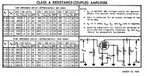
Thank you for the data sheet. i will use the plan x2 as two stages one into the other as a starting point to build.
Could I please ask a couple of questions to help get me started...
Q1, in note 4 it says Rc2 should be by passed. Does this note refer to Cc2 to ground or should i run a cap in parallel with Rc2? if so what type and value range would work?
Q2, to lower the gain is it ok lower the value of Rgf ?
Q3, if i build two of these stages with a VR in between, should i change the 100k impeadance resistor on the second stage to better be able to accept the signal from the first stage? if so what range ohms should i try?
Q4, will i need the coupling cap on the start of second stage as there is already another one near the end of the first stage?
Q5, Is there a general rule for where you take anode supply from in the B+ filter/resistor supply line for each stage?
ie, should the first stage take a higher voltage from the B+ first then the second stage take a slightly lower voltage further down the line after another smoothing/filtering cap.
Q6, is it possible to get an idea of what watt rating for the 5k-10k resistors i would need to use for the B+ Power supply only powering these two tubes?
sorry its quite a few questions but i think its all i need to know to get started and come up with a good working model.
i will post a proper well drawn working schematic for anyone reading this when i get it working/sounding good
http://www.mif.pg.gda.pl/homepages/frank/sheets/084/5/5654.pdf[/QUOTE]
Thank you for the data sheet. i will use the plan x2 as two stages one into the other as a starting point to build.
Could I please ask a couple of questions to help get me started...
Q1, in note 4 it says Rc2 should be by passed. Does this note refer to Cc2 to ground or should i run a cap in parallel with Rc2? if so what type and value range would work?
Q2, to lower the gain is it ok lower the value of Rgf ?
Q3, if i build two of these stages with a VR in between, should i change the 100k impeadance resistor on the second stage to better be able to accept the signal from the first stage? if so what range ohms should i try?
Q4, will i need the coupling cap on the start of second stage as there is already another one near the end of the first stage?
Q5, Is there a general rule for where you take anode supply from in the B+ filter/resistor supply line for each stage?
ie, should the first stage take a higher voltage from the B+ first then the second stage take a slightly lower voltage further down the line after another smoothing/filtering cap.
Q6, is it possible to get an idea of what watt rating for the 5k-10k resistors i would need to use for the B+ Power supply only powering these two tubes?
sorry its quite a few questions but i think its all i need to know to get started and come up with a good working model.
i will post a proper well drawn working schematic for anyone reading this when i get it working/sounding good
Attachments
Last edited:
Paul - even one pentode has a lot of gain. Running one high-gain pentode stage into a second high-gain stage might have too much gain, along with too much hiss, and too much tendency to microphonics and oscillation.i will use the plan x2 as two stages one into the other as a starting point to build.
Those datasheets date from a time when pentodes were a new and expensive luxury, capable of much more gain than any triode that had come before. I think designers were caught up in their newfound ability to get tons of voltage gain out of a single stage, the idea being that you could use fewer stages than you'd need with a triode.
And those designs in the datasheet were probably going to be used with a record player, or reel-to-reel tape recorder, or something else which never got as loud as an electric guitar. They would probably have been fine in that application. But for guitar, input pentodes usually seem to go with intolerable microphonics - the Internet is full of stories about this problem, both for DIY and commercially manufactured amps.
Commercial amp designs using pentodes at the input tend to have short lives as commercial products - either the whole model disappear from the manufacturers lineup, or the model name remains, but the pentode disappears from the input stage!
You don't have to use those datasheet values and set up those pentodes for enormous gain, though. If you lower the B+ voltage, lower the anode resistor, and lower the screen grid voltage to get the DC bias to work out right, you can usually manage to get much lower gain.
Merlin Blencowe has an excellent write-up on how to design a small-signal pentode gain stage on his website: The Valve Wizard -Small Signal Pentode
The note refers to Cc2 to ground. The screen grid must be at signal ground, otherwise you get very little gain (too little!) from a pentode.Q1, in note 4 it says Rc2 should be by passed. Does this note refer to Cc2 to ground or should i run a cap in parallel with Rc2? if so what type and value range would work?
That will lower gain, but also lower output headroom. You can make replace Rgf with a pot, and use it to set gain, and this will have fewer downsides. It may help with microphonics and excessive gain problems, and is quick and easy, so probably worth a try.Q2, to lower the gain is it ok lower the value of Rgf?
What's a VR? Virtual Reality? Vintage Raisin? Vigorous Rat?Q3, if i build two of these stages with a VR in between, should i change the 100k impeadance resistor on the second stage to better be able to accept the signal from the first stage? if so what range ohms should i try?
")
Did you mean a potentiometer?
To answer your question, you can probably increase the 100k input resistor - the max tolerable value is usually specified somewhere on the datasheet. Usually up to 1 Meg is safe; you may be able to go higher in some cases.
No. If you're going to use a pot in between the two stages, the pot wiper will already be at 0V, which is also where the input grid of the next stage needs to be.Q4, will i need the coupling cap on the start of second stage as there is already another one near the end of the first stage?
No general rule; each additional RC filter reduces AC ripple on the B+ line. Each RC filter also reduces unwanted signal coupling between gain stages (via the power supply rails) that might otherwise cause instability at low frequency (aka motorboating).Q5, Is there a general rule for where you take anode supply from in the B+ filter/resistor supply line for each stage? ie, should the first stage take a higher voltage from the B+ first then the second stage take a slightly lower voltage further down the line after another smoothing/filtering cap.
The fact that each RC stage drops the DC voltage is more of an unwanted side-effect in many cases.
Power (watts) = current x current x resistance; current in ampsm, resistance in ohms.Q6, is it possible to get an idea of what watt rating for the 5k-10k resistors i would need to use for the B+ Power supply only powering these two tubes?
If, for instance, your two tubes draw a combined 0.01 amp (that's 10 mA), and you use a 10k (that's 10,000 ohms) resistor, the power dissipated in the resistor will be (0.01 x 0.01 x 10000), or 1 watt. A good rule of thumb for resistors is to use them at no more than half their rated power handling capacity. So, in this example, you would want to use a 2 watt, 10k resistor. (You could use a 5 watt, 10k resistor, it will run cooler, but also be bulkier and cost a bit more.)
-Gnobuddy
- Status
- This old topic is closed. If you want to reopen this topic, contact a moderator using the "Report Post" button.