Hello Guys, another fine day playing with amps.
I'm working on a valve king that is plagued with 120Hz hum. I know for sure that the signature is firstly 120Hz, having used a smartphone-based spectrum analyzer. The PT mechanically vibrates, presumably 60Hz - and has been replaced - and the replacement Peavey sent along vibrates just as bad. All filter caps have been replaced before this issue.
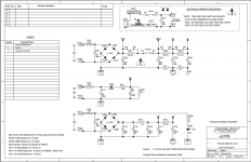
I thought the real suspect was the series heater string. Peavey DC filtered the filament supply with a full wave plus 4200uF total capacitance. The 3 preamp tubes are run in parallel. I found 768mVpp of sharp-edged ripple on pin 9 (DC input, pins 4/5 ground) of the first two preamp tubes. This seems like a lot to me, so I added 6600uF to the filtering supply. This changed the amount of ripple AND the DC voltage on the tube heaters a bit, but the amp does not seem to be impaired sound-wise by this change at all. Unfortunately, the level of 120Hz hum has not changed, either. I also replaced the rectifier diodes in this circuit, unnecessarily.
In addition, as this DC filament supply circuit has two extra branches stemming from it, to power the reverb IC's and the power LED, I disconnected both of them to test for hum reduction at the speaker. These branches do not draw much current and they have no effect on the hum level.
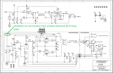
Attached is the schematic.
I'm working on a valve king that is plagued with 120Hz hum. I know for sure that the signature is firstly 120Hz, having used a smartphone-based spectrum analyzer. The PT mechanically vibrates, presumably 60Hz - and has been replaced - and the replacement Peavey sent along vibrates just as bad. All filter caps have been replaced before this issue.
I thought the real suspect was the series heater string. Peavey DC filtered the filament supply with a full wave plus 4200uF total capacitance. The 3 preamp tubes are run in parallel. I found 768mVpp of sharp-edged ripple on pin 9 (DC input, pins 4/5 ground) of the first two preamp tubes. This seems like a lot to me, so I added 6600uF to the filtering supply. This changed the amount of ripple AND the DC voltage on the tube heaters a bit, but the amp does not seem to be impaired sound-wise by this change at all. Unfortunately, the level of 120Hz hum has not changed, either. I also replaced the rectifier diodes in this circuit, unnecessarily.
In addition, as this DC filament supply circuit has two extra branches stemming from it, to power the reverb IC's and the power LED, I disconnected both of them to test for hum reduction at the speaker. These branches do not draw much current and they have no effect on the hum level.
Attached is the schematic.
Attachments
Last edited:
Problem Solved... or good progress made.
I just learned two things:
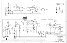
1) A large source of the mechanical hum is being generated by a tiny ceramic cap! I've heard of these things being microphonic, but this is the first time I've seen one become a speaker. The cap is C201, and it is shunted across the AC legs of the main rectifier diodes. I can use hot glue to minimize the vibrations, correct?
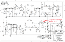
2) I was reading DIYaudio posts earlier today, and I came across a novel idea (in that the one I built has nine pins") ) - using a Heater Dummy Tube to troubleshoot series-filament circuits. I cut all but the three heater pins off of a poor conducting 12AU7, then used it in the PI slot to separate the pre/pwr amp signal portions of the board, further isolating the source of the 120Hz hum. No 120Hz here, so I moved it down to V2 and placed the good V3 back in the circuit and found that 100% of the hum level was being generated from here forward. Then, I lowered the level of the hum by 3dB in moving a long shielded signal wire for V3. It was zip tied on top of the main filter caps. I'd like to see if I can lower it some more, but it might be time to call it a finished job - the customer didn't bring the amp in for hum, even though it did need, and get a fix. (*Disclaimer: the issues the customer mentioned have been corrected.)
) - using a Heater Dummy Tube to troubleshoot series-filament circuits. I cut all but the three heater pins off of a poor conducting 12AU7, then used it in the PI slot to separate the pre/pwr amp signal portions of the board, further isolating the source of the 120Hz hum. No 120Hz here, so I moved it down to V2 and placed the good V3 back in the circuit and found that 100% of the hum level was being generated from here forward. Then, I lowered the level of the hum by 3dB in moving a long shielded signal wire for V3. It was zip tied on top of the main filter caps. I'd like to see if I can lower it some more, but it might be time to call it a finished job - the customer didn't bring the amp in for hum, even though it did need, and get a fix. (*Disclaimer: the issues the customer mentioned have been corrected.)
I just learned two things:
1) A large source of the mechanical hum is being generated by a tiny ceramic cap! I've heard of these things being microphonic, but this is the first time I've seen one become a speaker. The cap is C201, and it is shunted across the AC legs of the main rectifier diodes. I can use hot glue to minimize the vibrations, correct?
2) I was reading DIYaudio posts earlier today, and I came across a novel idea (in that the one I built has nine pins
) - using a Heater Dummy Tube to troubleshoot series-filament circuits. I cut all but the three heater pins off of a poor conducting 12AU7, then used it in the PI slot to separate the pre/pwr amp signal portions of the board, further isolating the source of the 120Hz hum. No 120Hz here, so I moved it down to V2 and placed the good V3 back in the circuit and found that 100% of the hum level was being generated from here forward. Then, I lowered the level of the hum by 3dB in moving a long shielded signal wire for V3. It was zip tied on top of the main filter caps. I'd like to see if I can lower it some more, but it might be time to call it a finished job - the customer didn't bring the amp in for hum, even though it did need, and get a fix. (*Disclaimer: the issues the customer mentioned have been corrected.)TankAudio, that's an interesting story. If the 120Hz is coming from C201 then that indicates it is the diode turn-off spikes that are causing internal stress, rather than the 60Hz sine wave that is also imposed on that capacitor.
If the diodes are 1N4007, then replacing with UF4007 may take some of the 120Hz stress away from C201. As a best fix process, a tuned snubber (C plus another RC across the secondary) would help even further. But it could just be a poor C201 - although replacing it needs a suitably rated cap - perhaps a poly cap rather than a ceramic.
If the diodes are 1N4007, then replacing with UF4007 may take some of the 120Hz stress away from C201. As a best fix process, a tuned snubber (C plus another RC across the secondary) would help even further. But it could just be a poor C201 - although replacing it needs a suitably rated cap - perhaps a poly cap rather than a ceramic.
Thanks Trobbins and DJGibson,
I actually have uf4007's in stock, I will give them a try. The 120Hz that emanates from the ceramic capacitor can also be felt in the main filter capacitors. Is it crazy to believe I felt it in the transformer as well? It does make sense to me that the piezo-electrical effects caused by the rectifier diodes would be carried both forwards and backwards into the circuitry.
Now that my brain is on to something totally new with this idea of stress being caused by the turn-off spikes of diodes, can it be explained why THIS PARTICULAR AMP produces the effect so strongly? I'm sure I will learn more about snubbers and their use in shunting the windings of transformers through this process.
A question, does the capacitor C201 shunted across the secondary windings perform the same job as a single ceramic capacitor placed in parallel with each of the four rectifier diodes, as found in other amp designs?
One more thing,
In reference to the long shielded cable in my last post, this cable is leaving the effects loop as it heads to V3. When I connected the effects loop with a patch cable, a ton of hum vanished. How does this happen?
Can you identify the shielded wire on the schematic? It could be the cathode related connections, or the input grid. Either way, separation and distance of the shielded wire from anything high-voltage or high signal or transformer related is your friend.
C201 just could be a poor ceramic, or its mounting layout could allow resonant vibration.
I personally think diodes shunted with parallel capacitors was a poor knee-jerk method to try and reduce rectifier noise in days of yore - it poorly manages the root cause of the issue.
Some background tech discussion buried in https://www.dalmura.com.au/static/Power%20supply%20issues%20for%20tube%20amps.pdf
Ciao, Tim
High impedance sections of circuitry are very prone to picking up nearby AC voltage signals. It may be the level of screening provided by the shield in the cable, or the length of unshielded signal wire at the end, or induced current in the shield itself, or a poor shorting connection in the return socket.
If possible, run the shielded cable as close to chassis for as long as possible, rather than letting it hand in the air, may help.
Unsure if that signal passes through the P301/P311 connector.
If possible, run the shielded cable as close to chassis for as long as possible, rather than letting it hand in the air, may help.
Unsure if that signal passes through the P301/P311 connector.
Connector technology matters. Peavey used punch-down blocks for a long ground wire in another product, a technology that goes high resistance after a decade or two due to oxide. (PV-8.5, PV-1.3k) Check that the shield of the cable is actually connected to the point it is supposed to be connected to. Solder joints are expensive but reliable - out of fashion in mass market products like this. Punchdown works for a while, but most grounds don't have enough current or voltage to burn the oxide off. <24 v & < 50 ma is a "dry connection" deltrol relay used to say in their catalog. Molex KKR was the specific connector that drove a PV-8.5 owner crazy with hum.
Last edited:
I am wondering how much of those Molex connector woes could be eliminated by substituting GOLD pins for the tin ones?Connector technology matters. Peavey used punch-down blocks for a long ground wire in another product, a technology that goes high resistance after a decade or two due to oxide.
Forget gold, use silver. As we used to do.I am wondering how much of those Molex connector woes could be eliminated by substituting GOLD pins for the tin ones?
Solder is still better.
Farnell stocks gold plate pins, not silver. I bought some but since the wire is copper, I don't have much hope it would help: Prevent oxide signal blockage on the feedback & VI limiter pins. The valvestate 50 of the OP, probably removing and replacing the shield in the punchblock on the wire he replaced temporarily with clip leads, would stop the hum for a decade. Shields that aren't grounded at one end make great antennas.
Soldered joint is gas tight so cant corrode.Solder is still better.
- Status
- This old topic is closed. If you want to reopen this topic, contact a moderator using the "Report Post" button.
- Home
- Live Sound
- Instruments and Amps
- 120Hz hum in Peavey Valveking 112 - Filter caps already replaced