As I understand it, the original tetrode design was largely unusable, because it had those huge "kinks" in the curves that you mentioned.From memory, the Tetrode added a screen between grid and anode, while the Pentode went one further
Phillips fixed this with the third grid, called the result a pentode, and patented the concept. Pentodes were hugely superior to triodes in many applications (RF and power output among them), and everybody wanted to manufacture them. But you had to pay Phillips a licensing fee to do that.
Then someone figured out how to modify a tetrode in a superficially very subtle way (line up the grid wires precisely) that actually produced spectacular results: the kinks in the characteristic curves went almost completely away, and now these new-fangled tetrodes were as good as a pentode, and best of all, you didn't have to pay Phillips a licensing fee to build them!
The good properties come from the ballistic properties of the searchlight-beams of electrons flying between the aligned grid wires inside the valve, so these valves are variously called "beam tetrodes" or "beam power tubes". The theory behind their operation is considerably more sophisticated than preceding generations of valves, but that seems to have been forgotten later, and nowadays most people seem to just call them pentodes. Which, quite literally, they are not!
You might also find references to "beam deflecting plates", but these actually have nothing to do with the actual beams that cause the "beam tetrode" characteristic. Those deflecting plates were only used in early generations of beam tetrodes, which had flattened cathodes which only emitted significant numbers of electrons in two directions. Later, and better, beam tetrodes used cylindrical cathodes, with electrons emitted radially in all directions. No beam deflecting plates in sight.
I got interested in valve guitar amps a few years ago, and at first I didn't know there was any difference between one pentode and another. But I was very curious why EL84s sounded so different from 6V6s (I like the latter a lot more).
So I dug deeper, and found that a lot of good information had been largely lost to history in the last several decades. It turns out pentodes and beam tetrodes do have some fundamental differences in characteristics. From our guitar-centric point of view, the one most likely to matter is the inherently different harmonic spectrum.
(There is a research paper by Schade on the theory and design of the original 6L6 beam power tube; somewhere in there is a rueful acknowledgement that beam power tubes have more 2nd harmonic distortion, but the authors go on to say that this is not as much of a problem as it seems, because even harmonics cancel out in a push-pull output stage.)
This, of course, was when tubes were used for Hi-Fi and RF work, and linearity was a good thing.
Things are different for us guitarists!
I can imagine Phillips management grinding their teeth after their patents ran out, and pesky American manufacturers began to sell "pentodes" that didn't even have three grids!, but there were copyright issues which caused some valves to be 'mismarketed', shall we say.
The 6V6 is a beam power tube / beam tetrode, and as you say, overpowered for a preamp application.From my side of the pond, the 6V6 is a pesky American 'tube'
<snip>
They'd be overpowered for this application, would they not?
Which is why I mentioned that there are small-signal beam tetrodes out there, often cheap. But the datasheets almost always called them "pentodes", so it is hard to tell which types they are!
One way to tell for sure is by inspection with a magnifying glass (or, I suppose, cracking the envelope open
)Theory says that there might be detectable differences in the characteristic curves (a sharper corner at the top left of each curve for beam tetrodes), but I've looked at a lot of datasheets where the differences aren't evident to the eye.
My research so far has turned up two little "pentodes" that are actually beam tetrodes: one is the little 7-pin 6AG5, the other is the supposed "pentode" in the 9-pin 6JW8.
While manufacturers datasheets call the 6AG5 a "pentode", one website does agree with my magnifying lens: it's a beam tetrode! (6AG5 @ The Valve Museum )
I like the sound of a 6AG5, it seems to easily produce lovely shimmery clean tones. They tend to be dirt cheap, too, at least in the USA. To me, they are kinda-sorta small-signal 6V6 equivalents. And a lovely little secret to have, given the insane pricing of NOS 6V6 valves.
I have the feeling you prefer a lot more distortion than I do, so a true pentode (like the EF86) might be more to your taste than the 6AG5 - it's more likely to growl, like a good rock guitar amp should.
In the USA, there are also small-signal (true) pentodes that are unloved and dirt cheap, but which sound great. The little (7-pin) 6AK5 is one example. Nobody ever used one in a "classic" guitar amp, so nobody thinks they are worth anything...
-Gnobuddy
Since this thread is about getting good distorted guitar sounds at neighbour-friendly SPL levels, I'd like to throw in a surprise contestant.
Take a listen to this guitar clip. (Not the somewhat erratic playing technique, just the guitar tone): http://www.diale.org/mp3/v1.mp3
What sort of awesome valve guitar amp do you think made those sounds?
Maybe this one? (try 9 minutes into the clip): YouTube
Well, no. The real answer is here (including the link to the first sound clip in this post): 2BJTE - 2 BJT triode emulator
(Disclaimer: This is NOT my work. And I have not built and tried this out yet. But it is definitely on my list.)
-Gnobuddy
I have the feeling you prefer a lot more distortion than I do...
-Gnobuddy
Hi,
This is the big question, isn't it. What you consider 'hi-gain' might be 'early break up', as far as I'm concerned
.So difficult to describe in words, but we may not be so far apart. I prefer to drive the 'clean' channel of an amp into power amp overdrive - think Vox Ac15 or Marshall 18W - for a crunchy 'classic' rock sound. Back off the volume for the cleaner passages, step on a treble booster for the leads.
I'd call thet a Classic Rock set up, and you're spot on about the EL84's. That was never a conscious choice though, just most British amps use 'em.
I had a Selmer Treble 'N' Bass 50, with EL 34's, which may have been my favourite amp of all, but was old and kept finding new ways to die.
Marshall JCM800/Soldano Super Lead style cascading gain stage amps are not my bag normally, but I'm coming around to the idea that not all pre-amp gain is equal. It's becoming increasingly apparant that to get a 'good' sound at bedroom levels, I'll need more pre-amp gain than I'm used to.
Aside from that, many thanks for another informative post. I've still got a lot of thinking to do on this project, but I feel like I'm getting close to a workable starting point.
Regards,
Matt.
A couple of things:
a/ That schematic is copyright information
b/ It's a great sounding amp
I would take the front end of an '800 (2203) with master vol and marry it to the 1W back end.
cheers
Terry
The schematic is drawn up by Matek and has about five different revisions, which one or part are copyright information?
Your welcome.
Member
Joined 2009
Paid Member
...I dug deeper, and found that a lot of good information had been largely lost to history in the last several decades....
Still lost. You might re-review the multi-grid family tree.
First: at least in practice, there are two applications. Small signal and power.
Small triode radio amplifiers oscillate from plate-grid feedback. If you put a grid between and ground it, no electrons flow to the plate. If it is an open grid and tied to a medium-high voltage, electrons flow and feedback is greatly reduced. The plate can't swing below G2, but in small-signal that is a minor problem compared to a radio that mostly transmits.
In Power, it is a problem, not having full plate swing. Actually for HIGH voltages (actually high impedance, which is easier in radio than audio), you can put G2 at 400V and Plate at 2,000V and get near-full swing, OK. But audio tends to like fairly high current with its voltage.
The problem is that the G2-P space fills with secondary electrons splashed off the plate. If plate is not most-positive, they go to G2.
A third grid at low potential can shield this electron storm. Now the plate can swing very low.
It does not have to be what we call a grid. Actually there can be a Critical Distance from G2 to plate where a negative region forms. Or two side-rods can induce a negative region. While it is all about the same to the electrons, it looks different on the patent drawings. RCA bought several of these ideas.
Then there is Aligned Grid. G2 tends to steal a significant fraction of the cathode current. Overall you come out ahead of a triode because of the deep plate swing. However as long as RCA was re-inventing (to dodge patent) they also bought the idea to hide G2 in the shadows of G1. You would think that just winding the same pitch would do that. But if you wind grid wires around grid rods of different spacings, the slant is different. RCA built a machine which cuts diagonal notches in the G2 rods so the grid wire does not just wrap, it jogs, and ends up same-slant as G1 wire. This is a fairly expensive thing to do in production, which is why the EL34-family remained popular even after these patents expired and competitors built grid-jog lathes for 6L6-family tubes.
All of these tricks can be bent one way or another. I don't think you can "tell" which construction from data. The pentode knee can be high or low (relative fraction of Vg2), sharp or broad, dippy or not.
There were a few TV Tuner tubes which were odd. Low noise (snow) suggests triode. Good stable gain with that leads to two triode cascode. But there were some "tetrodes" with internal side-fins which reduced grid-plate feedback low-enough, and without reducing current, and apparently without being kinky. These may only work good for the mV signals of a tuner; I have never played with one.
I was looking to go down something similar to your Firefly route.
However, given the advice I've had here, and the fact that you weren't too smitten with the Firefly I'm starting to reconsider. Biting the bullet and accepting a little more preamp gain seems the sensible route. After all, there's no substitute for genuine power and ear crushing volume...
What was it about the Firefly you didn't like?
I didn't get on with the _original_ Firefly topology as per Doug's schematic with some alterations (AX84 Firefly-style build – Tristan Collins ).
I think this was due to:
- no master volume
- the cascode at the front hitting the next stage too hard
- VVR of the whole amp was a truly terrible idea
So whilst it gave nice clean tones with the boost off, I didn't like the boost and the thing was way too loud for my needs.
Hence I went down the simpler 3 stage + CF tried and tested route. Lots of preamp gain / distortion for playing whilst watching TV etc. This thing sounds huge for its size. Lower preamp voltages help with that I believe.
Also, lowering the CF load resistor away from 100k helps as Merlin discusses in the book - no need to hit the output stage with a huge swing and this might make up for the lack of phase inverter distortion.
Merlin's Bone Ray tone stack is really useful as well. I end up running the tilt at 90% and about 20% on the middle for heavy stuff. And more around 50% for normal rock. I can set it for heavy sounds and clean up / control from the guitar easily - no need to move from the sofa or put pedals up front!
It was a fun build (my first point to point), and didn't take too many tweaks to get it 'right'.
If you're interested, I have some PCBs for general preamp stages / tone stack / CF left over - Merlin and I designed similar things at the same time. His no doubt better... You could whip up something really quickly with them, and come up with a few interchangeable options... AX84.com - The Cooperative Tube Guitar Amp Project
You might re-review the multi-grid family tree.
What PRR said about pentodes and patents is 100% correct. Much of this is explained in the old RCA tube manuals. Pages 5 through 10 in the RC30 edition are worth reading. I have a few additions.
Most EL34's are true pentodes with three spiral wound grids. They typically eat more screen current than "beam power tubes" when operated under similar conditions. I have seen some EL34's that do have aligned grids, and their screen current is far lower. I have also seen a few "EL34's" that were beam tubes, but they don't exist right?
The EL34 was a pure pentode of UK and European origin. When they became popular in the USA, Sylvania simply rebranded Mullard made tubes.....for a while. Then they introduced the 6CA7, which was a beam power tube, and according to Sylvania, it was compatible yet "better." For use in Marshall amps that ate tubes, the "fat bottle Sylvania 6CA7" is prefered by many users for longevity. The cross breeding of the lineage occurred when vendors started making tubes with both numbers on them. These could be mongrels with anything inside them. Some of these mongrels are just labeled EL34.
The true pentode, big or small, has three spiral wound grids. A "beam tube" has two spiral wound grids and a beam forming plate, which is a closed metal box, connected to the cathode, ground, or in special cases a small positive voltage. This box has a window opening in it through which all plate current must flow. As stated this was primarily "invented" to dodge a patent, but has been tweaked for good purpose over the years. I call these "beam tubes" because the terms "beam tetrode," "beam pentode", or just "pentode" have been used to describe the these tubes over the years since the pentode patent expired.
A true pentode with a round cathode and round plate will have electron flow in nearly a circle, yes the flow is greatly reduced in the shadow of the grid rods. This is desirable in many small signal pentodes for noise control, especially at RF frequencies. For a power output tube it can be a problem because the electron flow will not be evenly distributed across the entire plate structure unless everything inside the tube is perfectly concentric. No tube is perfectly aligned, so hot spots will develop in areas where the electron flow is the highest.
The beam forming electrode can be used to form the electron flow into a beam which is confined to a smaller area of the plate. On high powered tubes this is usually the seam area where the two plate halves are joined. The seams are often folded outward and extended to create heat radiators. This is the reason for the plate dissipation increase from the 6L6GB to the 6L6GC. Some vendors have added additional heat radiating fins in this area to further improve heat dissipation.
Note that the outer shell that you see when looking through the glass on many small signal tubes, particularly those originally intended for use as RF or IF amplifiers is NOT the plate. It is an outer shield usually internally connected to the cathode or G3. The plate in these tubes is usually two small rectangles inside this shield to reduce it's capacitance. These tubes are sometimes actually beam tubes regardless of what the book says.
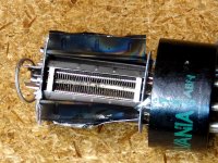
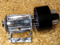
Here are pictures of two beam power tubes that I have dissected. As you can see they were quite dead before I smashed them.
The Sylvania 6V6GTA was gassy so I just turned up the power supply and watched it fry. I have peeled back the plate (black) to show the bent cathode, what's left of the control and screen grids, and the beam forming "box" with its window (silver). Note that the cathode in this tube is nearly round. Beam control is done entirely by the beam forming electrode.
The 6BQ6GA died from a screen drive experiment gone wrong. This little guy was half of a push pull pair busy cranking out 125 watts before a tube arc ended the fun and blew up a bunch of other parts in the process. The other tube survived. Here I tore the plate completely away and opened up the beam former to find out where the arc took place. I would guess that it was right where the screen grid rod melted in half (upper right).
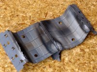
The plate is also shown. Note that there are actually 3 pieces of metal in the plate sandwich. The center piece extends slightly into the internal plate cavity. This is not for heat radiation, but to cure an oscillation mode particular to TV sweep circuits. Some larger sweep tubes may have two or three internal fins. Often these fins do extend outside the plate area for heat radiation purposes. It is between the screen grid rods, and both of these internal fins that the arc happened.
Attachments
Thanks to PRR and George (Tubelab). Lots of fascinating stuff there.
And we haven't even mentioned some of the weirder vacuum devices like heptodes. There was another weird one I stumbled across a few years ago that used control electrodes to steer electrons (from a single shared cathode) between either one of two anodes. I can't remember what this was called, or what its intended application was (RF mixer?).
My understanding is that the "beam" in "beam power tube" is actually the sheets of electrons squeezing between the aligned grid wires. The beam forming plates used in early beam power tubes constrained the electron flow in the perpendicular direction to simplify manufacturing in earlier devices, but were evolved away in later generation beam power tubes, which had full cylindrical symmetry, and no beam forming plates.
I found a well-written 'Web page that described this evolutionary history of beam power tubes a few years ago, but have since lost the bookmark, and the newly ruined Google can no longer find it.
-Gnobuddy
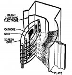
Here is the picture from the 1939 article by RCA introducing the new 6L6 tube. It has been reprinted in almost every edition of their tube manual since then. The picture shows the electron streams seperating as they pass through the grids, then recombining as they head toward the plate.
Heptode......5 grids (7 elements) most often found in the form of a pentagrid converter, a tube used in AM radios as the mixer / oscillator. The common flavors are 6SA7 old octal radios, and 6BE6 in mewer 7 pin miniature radios. The 6BE6 makes a nice triode is you wire all the grids together.
Hexode......4 grids (6 elements). To make matters more confusing, there exists at least one "beam hexode", the 6GU5. They make nice preamp tubes, I plugged them into a 6CB6 pentode socket to get more gain.
There are a few gated beam, or beam deflection tubes around for various uses. The most common was for demodulating a phase modulated color signal in TV sets. The best undocumented use? An audio compressor. There are types (I can't recall the numbers right now) that stack the steering plates on top of a pentode. Use the pentode to amplify the audio, then steer that audio stream to one of two plates, or spread it between them. Use one plate for the output. That way you can vary the output level without the distortion associated with variable Mu devices.
mentioned some of the weirder vacuum devices like heptodes.
Heptode......5 grids (7 elements) most often found in the form of a pentagrid converter, a tube used in AM radios as the mixer / oscillator. The common flavors are 6SA7 old octal radios, and 6BE6 in mewer 7 pin miniature radios. The 6BE6 makes a nice triode is you wire all the grids together.
Hexode......4 grids (6 elements). To make matters more confusing, there exists at least one "beam hexode", the 6GU5. They make nice preamp tubes, I plugged them into a 6CB6 pentode socket to get more gain.
I stumbled across a few years ago that used control electrodes to steer electrons
There are a few gated beam, or beam deflection tubes around for various uses. The most common was for demodulating a phase modulated color signal in TV sets. The best undocumented use? An audio compressor. There are types (I can't recall the numbers right now) that stack the steering plates on top of a pentode. Use the pentode to amplify the audio, then steer that audio stream to one of two plates, or spread it between them. Use one plate for the output. That way you can vary the output level without the distortion associated with variable Mu devices.
Attachments
A simple Amp from 1940's which you may wish to clone/copy.
Historic Harmonica Amplifier
Currently has a triode strapped 6J7 into a pentode mode 6J7 into a 6V6.
Maximum use is made of the 2nd stage pentode as it allows the clever tilt tone control via feedback around the 6V6.
No reason it could not be made using 12AX7 Triode input (paralle the triodes if you like) to an EF86 to 6V6. Solid State rectifier (or 5Y3) OK.
I used that Amp with my Tele for a while and was most impressed.
A guy her in Oz cloned it exactly (except did not use filed coil speaker) and he was likwise impressed.
Cheers,
Ian
Wow, someone reads my site!
But of course! Amps that can produce tasty sounds at neighbor-friendly levels are (or should be) a high priority for most musicians who live in crowded cities.
I'd recommend the Merlin High Gain Preamp + Firefly Output.
The clarification is most appreciated, thank you.
kr, jonathan
Maximum use is made of the 2nd stage pentode as it allows the clever tilt tone control via feedback around the 6V6.
Years ago I tried sticking the typical TMB tone stack in the feedback loop (OPT secondary to PI) of a typical Marshall style guitar amp. While it did make for some cool and unique sounds, it also made for a rather loud and uncontrolled power oscillator at some settings. The phase shift of a $16 OPT and the tone stack added up to positive feedback.
I have used plate to plate feedback with just a resistor in HiFi amps, usually plate of output tube(s) to plate of driver tube(s).
I had never thought to try combining these two. There is no reason why this couldn't be done in a pentode preamp section either. I guess some more experiments are in order.
Gnobuddy;5327965 Snip... In the USA said:Hundred Buck Amp Challenge thread, page 70-posts 691 & 692, page 83-post 824.
Still using it.
(Sorry 'bout the Word doc)
Last edited:
Good evening all,
First up, thanks to everyone for your suggestions and help over the past week or so. I'd hoped to have had more time to spend on this but life/work/etc. intervened, as ever.
There's a lot been said that interests me, much of which is not reflected below!

Much of the above (especially in the output stage) was pencilled in before I started the thread, I'd consider it a starting point rather than a final destination.
Some of the values are more or less arbitrary, and I've lifted the tone stack and 'Boost' wholesale from Merlin's book. I'm not trying to re-invent the wheel, and I'm certain he understands filters and interstage coupling a good deal better than I do.
The pre-amp stages I've designed from the ground up. Again, they're hardly ground breaking but I think they're in the right ball park.
The ECC81 is more or less centre biased, providing enough gain to drive the EF86 (the other triode will drive the reverb circuit), while the EF86 is fairly warm biased, with slightly higher gain.
I'm still considering adding an extra gain stage (probably the other half of the ECC83 in the reverb recovery circuit) as a switchable gain boost between V1 and V2, but it might be prudent to test it without first.
As always, I appreciate the collective wisdom here and your thoughts and suggestions are welcome, particularly where the coupling is concerned. I'll work through it myself in time, but a (gentle) prod in the right direction would be grand.
As ever, you can also have a good laugh at how off my calculations are...
Regarding the output stage, the EL84 circuit I've included here is in some ways exactly what I was trying to avoid using, although it has the advantage of being convenient.
On gnobuddy's advice, I've been looking at the 6AK5 (seems we call them an EF95 over here). They certainly are cheap as chips, and look like a good candidate - I'll be investing in a few in the near future. The different pin out means I'd need to be sure I like them before committing to using them here, so they could be one to try out down the line, perhaps in a low output push-pull amp?
One thing at a time though...
Matt.
First up, thanks to everyone for your suggestions and help over the past week or so. I'd hoped to have had more time to spend on this but life/work/etc. intervened, as ever.
There's a lot been said that interests me, much of which is not reflected below!
Much of the above (especially in the output stage) was pencilled in before I started the thread, I'd consider it a starting point rather than a final destination.
Some of the values are more or less arbitrary, and I've lifted the tone stack and 'Boost' wholesale from Merlin's book. I'm not trying to re-invent the wheel, and I'm certain he understands filters and interstage coupling a good deal better than I do
.The pre-amp stages I've designed from the ground up. Again, they're hardly ground breaking but I think they're in the right ball park.
The ECC81 is more or less centre biased, providing enough gain to drive the EF86 (the other triode will drive the reverb circuit), while the EF86 is fairly warm biased, with slightly higher gain.
I'm still considering adding an extra gain stage (probably the other half of the ECC83 in the reverb recovery circuit) as a switchable gain boost between V1 and V2, but it might be prudent to test it without first.
As always, I appreciate the collective wisdom here and your thoughts and suggestions are welcome, particularly where the coupling is concerned. I'll work through it myself in time, but a (gentle) prod in the right direction would be grand.
As ever, you can also have a good laugh at how off my calculations are...
Regarding the output stage, the EL84 circuit I've included here is in some ways exactly what I was trying to avoid using, although it has the advantage of being convenient.
On gnobuddy's advice, I've been looking at the 6AK5 (seems we call them an EF95 over here). They certainly are cheap as chips, and look like a good candidate - I'll be investing in a few in the near future. The different pin out means I'd need to be sure I like them before committing to using them here, so they could be one to try out down the line, perhaps in a low output push-pull amp?
One thing at a time though...
Matt.
Last edited:
A simple Amp from 1940's which you may wish to clone/copy.
Historic Harmonica Amplifier
Snip...
Cheers,
Ian
Hi Ian,
Thanks for the link, looks like a very cool amp. The tone control is unusual, isn't it, is the idea of including it in the negative feedback loop to make it more linear?
Matt.
The tone control is via local feedback around the 6V6 output tube BUT not including the output transformer.
It is output tube anode to driver pebtode anode feedback sometimes called "Schade" feedback.
It has a second benefit in that it trades a little output tube gm for reduced rp. That gives some improvement in speaker damping.
Because of the output tube anode to driver anode feedback, you want high impedance looking down into the driver tube anode, so as to not divide the feedback voltage too much, hence a pentode driver rather than a triode driver. This feedback voltage division is not as bad as you might think looking at the value of that feedback resistor - why? because that feedback resistors value is "anti-bootstrapped" by having opposite phase signals at either side of it - that is, signal wise, it appears smaller than its actual value.
Doing it that way allows a one knob "tilt" control to be added into that feedback path. That is: flat at mid setting, treble cut and bass boost as you turn down and treble boost and bass cut as you turn up.
The tone control was nice but I particularly recall the the amp for its attack and "bite".
Very responsive to "digging in" on the guitar.
Cheers,
Ian
Last edited:
I've been looking at the 6AK5 (seems we call them an EF95 over here).
I have never tried the 6AK5 for an output tube. It does make a decent gain or preamp stage, but it's probably not a good candidate for the first stage due to microphonics. Some are worse than others in this respect, and the military flavors 5654, 6AK5W and 6096 are usually better, but some of them can be screamers too. A screamer is what I call a tube that is mocrophonic enough to start a feedback without a guitar plugged in! (combo, or head sitting on top of speaker)
The tone control is unusual, isn't it, is the idea of including it in the negative feedback loop to make it more linear?
Placing the tone control in the feedback loop makes it work "backwards." A treble cut is now a treble boost since the feedback is reduced at treble frequencies. It can also "tighten up" the sound at the frequencies being cut due to more feedback. I haven't tried this particular implementation yet, but it will be tested soon. See the warning below.
output tube anode to driver pebtode anode feedback sometimes called "Schade" feedback......you want high impedance looking down into the driver tube.....a pentode driver rather than a triode driver.
We could deal with a low impedance driver tube by lowering the feedback resistor, but the problem with a triode driver is the fact that it's plate resistance varies with the signal swing. This makes the feedback vary with the signal, causing more nonlinearities than it cures. Applying "Schade" feedback to a triode LTP, especially one with a CCS in it's tail usually works quite well. The unbypassed cathode raises the plate resistance into near pentode territory. I have done this in HiFi amps with extremely good results.
having opposite phase signals at either side of it
WARNING: A recent flaming failure in a hastily breadboarded high power HiFi amplifier has reminded me of another previous flaming failure. The "Schade" resistor is connected to the plate of the output tube and thus operates at B+ voltage with swings to at least twice B+ (much more in a guitar amp driven to clipping into a speaker load). Its other end is connected to the driver tube plate which will swing towards ground when the output tube's plate voltage peaks. The resistor should be rated for at least twice B+ voltage which is nearly impossible. The high power HiFi amp I am designing will use 4 X 500 volt resistors in series, but I took a shortcut in the breadboard and only used two. A hasty value swap from the top without removing the PC boards left the resistors too close to the board. The insulation failed causing an arc from the end of the resistor connected to the output tube plate to the ground plating on the PC board. Fed by a bench power supply capable of 1.7 amps at 650 volts continuously, the PC board got traces burned off, the resistor vanished, and the OPT is now a magnet.
An experiment in variable UL that wasn't well thought out used a pot connected across the OPT. It quickly proved that the Alpha pots sold by mouser will blow up if used in this manner.
The circuit shown in the harmonica amplifier runs the pot at B+ voltage. There are some series resistors that will prevent fireballs, but I would limit this type of circuitry to relatively low voltages unless the voltage ratings of all parts are known to be suitable. Many pots carry no voltage rating or are rated for 100 to 250 volts.
A quick look at the Mouser Alpha pot datasheet shows that the linear taper pots are rated for 500 volts, while the log pots are 250 volts. I don't remember which kind I blew up, because I didn't realize there was a difference until I just looked them up.
Matt, to be clear, I was thinking of the 6AK5 as a small signal pentode to be used in a preamp, rather than a power amp....I've been looking at the 6AK5
...They certainly are cheap as chips
...they could be one to try out down the line, perhaps in a low output push-pull amp?
By using a small-signal pentode as the last stage in a preamp, you can get pentode-flavoured distortion out of the preamp. The 6AK5 is a nice inexpensive alternative compared to the much better known (and much more expensive) EF86. It is quite simple to design a normal single-ended gain stage with a resistor as the anode load, just as you'd do with an EF86.
The 6AK5 is rated for no more than 180V (anode voltage), and the data sheets show only about 12 mA cathode current at the "knee" (zero grid voltage, top left corner of the curves.) This makes it challenging to use as an output device, because you need quite a high impedance output transformer.
If one is determined to use a 6AK5 as an output device, djgibson has shown that it can be done. But there are a number of (to use your words) cheap-as-chips small power pentodes out there with more current capability, so if one is going to buy pentodes for an output stage, I think one might as well make life easier by buying something that works with a more easily achievable output transformer impedance.
-Gnobuddy
Matt, to be clear, I was thinking of the 6AK5 as a small signal pentode to be used in a preamp, rather than a power amp.
Snip...
-Gnobuddy
Hi,
I had indeed thought you were recommending it as an power tube. At 0.5W max I did think it was a little on the low side, but I assumed there was something I was missing...
I'll re-evaluate it with preamp duties in mind.
Has 'cheap as chips' not made it across the atlantic? I don't think anyone's said it here either. Not since the 1950's, when chips were actually cheap.
The 'chips' in question are - to the best of my knowledge - potato chips (technically, chipped pototoes
). Broadly similar to what you would probably call 'Fries'; not micro chips, poker chips, or the things you call chips, which as we all know, are in fact 'crisps'.... Matt.
- Status
- This old topic is closed. If you want to reopen this topic, contact a moderator using the "Report Post" button.
- Home
- Live Sound
- Instruments and Amps
- Suggestions for a Medium Gain Guitar Amp Topology...