Hello there to each and every one.
I've been fiddiling around with analog audio circuits for some time now, and have made a few onboard preamps for my basses that I build.
Now, as my pedalboard seems to be growing bigger and bigger every year (no surprice there...) I'm having trouble to find a preamp pedal that suits my specific needs.
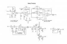
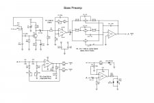
What I need is a high impedance input, a gain stage, 3-band eq and three seperate outputs. One output for the "dry" signal chain and two outputs with a high-pass filter, to feed the "wet" portion of the board (stereo chorus, stereo reverb, etc.).
So I've been searching the net for various circuits and have learn a lot about analog audio circuits, BUT some components I do not understand what they do and why they are in the circuit at the specific locations they are. Not to mention why that specific component has the value it has and how the value will effect the signal IF the value is changed.
Anyway, what I've done is put together a schematic using various circuits and I would appreciate if someone would care to take a look at it and comment on it.
A jpg file of the schematic is attached.
What's wrong with it? Will it go up in smoke if I build it and turn on the power?
Cheers,
"Bobby"
I've been fiddiling around with analog audio circuits for some time now, and have made a few onboard preamps for my basses that I build.
Now, as my pedalboard seems to be growing bigger and bigger every year (no surprice there...) I'm having trouble to find a preamp pedal that suits my specific needs.
What I need is a high impedance input, a gain stage, 3-band eq and three seperate outputs. One output for the "dry" signal chain and two outputs with a high-pass filter, to feed the "wet" portion of the board (stereo chorus, stereo reverb, etc.).
So I've been searching the net for various circuits and have learn a lot about analog audio circuits, BUT some components I do not understand what they do and why they are in the circuit at the specific locations they are. Not to mention why that specific component has the value it has and how the value will effect the signal IF the value is changed.
Anyway, what I've done is put together a schematic using various circuits and I would appreciate if someone would care to take a look at it and comment on it.
A jpg file of the schematic is attached.
What's wrong with it? Will it go up in smoke if I build it and turn on the power?
Cheers,
"Bobby"
Attachments
I can't anything wrong, for what that's worth.What's wrong with it? Will it go up in smoke if I build it and turn on the power?
")
Why not breadboard it, or at least the individual modules, and test them to see if they work (and sound) the way you want?
Is a maximum gain of 7 times (i.e. 60k/10k + 1) okay with your bass guitar and +/- 9V supplies? Still have some headroom left before clipping?
-Gnobuddy
The OPA chips are better inputs, and better outputs, than simple JFETs. Lose the FETs.
The OPA parts' DC error is low enough that I would skip output blocking caps. However your gain stage may multiply DC error, and I would stick a blocking cap after it.
Outputs to cables should have a few hundred Ohms series resistance.
This is configured for bipolar +/- supplies. That's often awkward on a pedalboard.
Attachments
Why not breadboard it, or at least the individual modules, and test them to see if they work (and sound) the way you want?
Is a maximum gain of 7 times (i.e. 60k/10k + 1) okay with your bass guitar and +/- 9V supplies? Still have some headroom left before clipping?
-Gnobuddy
Hi "Buddy"
My thought exactly. I know that the input buffer and the eq section works. The high-pass section is another question.
Speaking bout the high-pass section... Should there be a input buffer in front of the high-pass section?
The original circuit had a input buffer, but I removed it so I could use that op-amp for the output buffer for Output A.
Well, these days most electric basses have some sort of active electronics built into them (onboard preamps). They do boost the signal a bit, but not much. So therefore a LOT of gain is not neceserilly needed, I mean this is not a overdrive pedal. Besides, if you boost the signal too high in this pedal, it's possible that the effect pedal(s) that is connected after this pedal will clip.
However, you've got a good point there, this issue remains to be tested out in the future...
The OPA chips are better inputs, and better outputs, than simple JFETs. Lose the FETs.
The OPA parts' DC error is low enough that I would skip output blocking caps. However your gain stage may multiply DC error, and I would stick a blocking cap after it.
Outputs to cables should have a few hundred Ohms series resistance.
This is configured for bipolar +/- supplies. That's often awkward on a pedalboard.
Hi "PRR"
Youre right, I too would like to use only op-amps. If you think the JFET output buffers are not really needed, I will probably remove them.
However, the JFET input buffer is there to get that valve/tube-like sound that I'm after. What's YOUR experiences with JFET's and the sound of them?
Aaaa, ok. Didnt know that a gain stage can be "unstable" in that sence. Thanks for that info! However, the reason why I put a cap on the outputs is to protect the circuit(s) from static discharging that could occur in the long cables that are connected to the outputs. Is this a good idea or not?
Ok, so WHY should there be a few hundred Ohms series resistance on the outputs? There's one in the high-pass circuit too, but I dont know why...
Correct me if I'm wrong but it seems that this OPA2134 is designed to run on +/- supply rails only.
So I'm going to use a switched-capasitor voltage converter (the ICL7660) to get that -9V.
I've done this before and it seems to work, check it out on my website here; The Seven Seas
Cheers
It has to be fed from a low impedance output, yes - but your Output A is already low impedance. That means you don't need any additional buffer.Should there be a input buffer in front of the high-pass section?
Agreed. I have three bass guitars. None of them are expensive models. And all three have active electronics.Well, these days most electric basses have some sort of active electronics built into them (onboard preamps).
Exactly, and you could also clip this DIY bass preamp itself. Particularly if you like to slap and/or pop. Those sorts of playing techniques tend to put out a very "hot" signal, so you either have to turn the volume control on the bass down a lot, or have a lot of input headroom in your bass preamp...If you boost the signal too high in this pedal, it's possible that the effect pedal(s) that is connected after this pedal will clip.
Do you use a compressor with your bass? If so, will it go between bass and this preamp, or after the preamp? Compressors tend to be fussy about signal level.
-Gnobuddy
This is the sort of topic people argue about for days.However, the JFET input buffer is there to get that valve/tube-like sound that I'm after. What's YOUR experiences with JFET's and the sound of them?
I am currently building a small solid-state guitar (not bass) amp. For the guitar, my ears definitely prefer having a JFET at the input, preferably a common-source gain stage (rather than a source follower). I can't actually hear any "tube-like sound" with the JFET, but it does sound a little less harsh than an op-amp gain stage.
Here's the thing: modern op-amps are absolute engineering marvels. They are precise, accurate, and fast. So I have no doubt that a properly designed and powered (i.e., keep it out of clipping!) op-amp circuit will do a perfect, accurate, precise job of reproducing a guitar signal.
Meantime, a JFET common-source stage is not precise or accurate at all. Gain varies with signal. Big transients are probably "squashed" by this action.
So the fact that I prefer the sound of the JFET is not a criticism of op-amps. Rather, I think the truth is that electric guitar does not sound good if you reproduce its signal accurately. I think squashing the signal a little makes it sound more attractive and less harsh.
I have never built a bass amp or preamp, so I don't know if my ears feel the same way about bass. And of course, I have absolutely no idea how your ears feel about any of this!
So I would say this is another reason to breadboard your circuit and try it out before you build the final version. Maybe you'll want the JFET inputs, maybe you won't. Only you and your ears can tell.
Op-amps (and other high-gain, high feedback amplifiers) don't like having a capacitor connected directly to their outputs. But if you connect a length of guitar cable to the output, it has quite a lot of capacitance. This can drive the op-amp into instability, worst case.Ok, so WHY should there be a few hundred Ohms series resistance on the outputs?
Adding a few hundred ohms of series resistance, right at the op-amp output pin, removes the problem. The resistor buffers the cable capacitance from the op-amp, so it can remain stable.
It is possible to get around this: use two equal-value resistors across the power supply to create a 4.5V point, which then acts as the "0V" for the op-amp. In effect, you get a fake 0V ground, along with +/- 4.5V supply rails. This is done in a lot of guitar FX pedals.Correct me if I'm wrong but it seems that this OPA2134 is designed to run on +/- supply rails only.
However: 9V is really a small amount of voltage to run a guitar preamp on. I like your way (with 0, +9V, - 9V rails) better.
-Gnobuddy
It has to be fed from a low impedance output, yes - but your Output A is already low impedance. That means you don't need any additional buffer.
Do you use a compressor with your bass? If so, will it go between bass and this preamp, or after the preamp? Compressors tend to be fussy about signal level.
-Gnobuddy
Allright, I'll take your word for it...
Yes, at the moment I'm using the TC Electronic Spectra Comp. Finally I've found a small bass pedal compressor that you can adjust the threshold on! AND it is a 3-band compressor too. Happy days
Before the preamp, as most people do.
This is the sort of topic people argue about for days.
I am currently building a small solid-state guitar (not bass) amp. For the guitar, my ears definitely prefer having a JFET at the input, preferably a common-source gain stage (rather than a source follower). I can't actually hear any "tube-like sound" with the JFET, but it does sound a little less harsh than an op-amp gain stage.-Gnobuddy
So what are you saying here? Are you saying that a simple JFET buffer (a stage that NOT amplify the signal) does not sound "tube-like"? I think you are right about that. Been building the Tillman JFET for various projects and it seems it does sound "warm","round" and a bit compressed. Maybe its possible that to get that "tube-like" sound out of a JFET stage it HAS to boost the signal?
Here's the thing: modern op-amps are absolute engineering marvels. They are precise, accurate, and fast. So I have no doubt that a properly designed and powered (i.e., keep it out of clipping!) op-amp circuit will do a perfect, accurate, precise job of reproducing a guitar signal.
Meantime, a JFET common-source stage is not precise or accurate at all. Gain varies with signal. Big transients are probably "squashed" by this action.
So the fact that I prefer the sound of the JFET is not a criticism of op-amps. Rather, I think the truth is that electric guitar does not sound good if you reproduce its signal accurately. I think squashing the signal a little makes it sound more attractive and less harsh.
I have never built a bass amp or preamp, so I don't know if my ears feel the same way about bass. And of course, I have absolutely no idea how your ears feel about any of this! -Gnobuddy
I agree. But the question is "Are we trying to make the instrument (guitar, bass or whatever) connected to this preamp as perfect, accurate, and a precise job of reproducing instruments signal?"
Don't know about you, but I'm not. I'm not trying to build a high-end "hifi-like" preamp, I'm simply trying to build a preamp that sounds "good". "Good" in this case would be a "warm", "round" bass sound that still cuts trough the entire mix of the band. Easier said than done...
So I would say this is another reason to breadboard your circuit and try it out before you build the final version. Maybe you'll want the JFET inputs, maybe you won't. Only you and your ears can tell.-Gnobuddy
Yeah, gonna breadboard the high-pass circuit first to see how that performs.
Adding a few hundred ohms of series resistance, right at the op-amp output pin, removes the problem. The resistor buffers the cable capacitance from the op-amp, so it can remain stable.-Gnobuddy
Allright, got it. Thanks. That's one of the "wierd" things I've seen in schematics over the years and often wondered "What the *ell is that resistor there for?"
However: 9V is really a small amount of voltage to run a guitar preamp on. I like your way (with 0, +9V, - 9V rails) better.
-Gnobuddy
And speaking of that, I think I've run into a problem with the charge pump IC. The OPA2134 draws about 4mA per amp (according to the spec sheet). Using both amps in the chip will draw a total of 8mA:s. The max output current of the ICL7220 is 10mA:s. Adding another OPA2134 chip will raise the current drawn to about 12mA:s (IF using JUST one amp in the chip). Will the ICL7220 charge pump "blow up"? It might.
So I think I'd better find a charge pump chip that is capable of higher output currents, like the MAX634CPA.
My word is good on this one, because it's based on engineering fact: the reason you need a buffer before your active high-pass filter is because it (the high-pass) is sensitive to source resistance of whatever is feeding it. Any resistance there will affect your intended cutoff frequency, and also affect the "Q" of the filter.Allright, I'll take your word for it...
So, in order to work as designed, the high-pass needs to be fed from a low impedance source. And that's what you have at your output A.
Sounds good! I am pretty happy with this: ART Tube MP/C | SweetwaterFinally I've found a small bass pedal compressor that you can adjust the threshold on! AND it is a 3-band compressor too. Happy days
It is not specifically designed as a bass guitar compressor, but it works very well for me in that role. Gain and threshold are adjustable, as is output level.
Okay, then the preamp gain won't cause problems for the compressor. One less thing to worry about.Before the preamp, as most people do.
-Gnobuddy
To my ears, a JFET sounds better than an op-amp, but not as good as a real valve. And a JFET common-source gain stage sounds better (i.e. a wee bit warmer) than a source follower. But still not as good as a real valve (and I've tried to make it as good!)So what are you saying here? Are you saying that a simple JFET buffer (a stage that NOT amplify the signal) does not sound "tube-like"? I think you are right about that.
I think the trouble is the 100% negative feedback in a source follower. The feedback makes the JFET pretty linear. And linear is not what sounds best.
The Tillman circuit is set up for a voltage gain of somewhere between 2x an 3x. It has a lot of negative feedback, too, from the unbypassed 2.2k source resistor.Been building the Tillman JFET for various projects and it seems it does sound "warm","round" and a bit compressed. Maybe its possible that to get that "tube-like" sound out of a JFET stage it HAS to boost the signal?
I have used something very similar in my current project amp. Mine has a 47k drain resistor and 10k source resistor, which happen to be the right values to bias this particular MPF102 properly using a 24V supply. (JFETs have huge manufacturing variations, another MPF102 may need something other than 10k at the source to bias to the proper operating point.)
The trouble, I find, is the (relatively) low supply voltage that JFETs can tolerate. If you bypass that source resistor with a cap, the JFET immediately becomes less linear, more "tubey". But the gain also goes up, and so it will also overload and clip easily, and may not handle the full output from your bass.
A valve stage doesn't have the same trouble, mainly because you can run it from +300V rather than +/- 9V. There is a lot more output headroom before clipping.
So far, I cannot find a way to make a JFET sound as good as a real vacuum triode. I haven't yet explored using a small MOSFET along with a high voltage supply rail (+300 V if necessary.)
We are on the same page...imperfect amplification sounds better when it comes to guitars!I agree. But the question is "Are we trying to make the instrument (guitar, bass or whatever) connected to this preamp as perfect, accurate, and a precise job of reproducing instruments signal?"
Don't know about you, but I'm not.
You might try Amazon.com to see if you can find a DC-DC converter that does what you want. There are a tonne of positive voltage ones, but fewer ones that take a positive input and generate a negative DC rail from it. But you may get lucky and find what you need, a DC-DC converter that runs on +9V and generates -9V.And speaking of that, I think I've run into a problem with the charge pump IC.
-Gnobuddy
I took a quick look for you, and found these two:You might try Amazon.com to see if you can find a DC-DC converter that does what you want.
1) Amazon.com: Icstation DC Voltage Regulator Step Up Boost Converter Power Supply Module 3-10V to +-12V Postive Negative Dual Voltage Output: Industrial & Scientific
2) Amazon.com: DROK Mini Boost Voltage Converter DC 3.2~13V to DC +-15V Positive Negative Dual Volt Output Non-isolated Module 100mA Power Regulator Step Up Volts Transformer Board: Automotive
-Gnobuddy
To my ears, a JFET sounds better than an op-amp, but not as good as a real valve. And a JFET common-source gain stage sounds better (i.e. a wee bit warmer) than a source follower. But still not as good as a real valve (and I've tried to make it as good!)-Gnobuddy
Nope, there's nothing like real tube-amp. Had the pleasure to test out a Ampeg SVT II Pro (even the power amp is tube only) once. OMG! THATS what a bass amp should sound like!
Too bad it weighs 70 Pounds!Anyway...
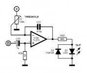
I saw this interesting looking schematic of a op-amp driven clip LED. See attached file. I do have one spare op-amp to use, so maybe it would be cool to use that op-amp to drive a clip LED? Don't know, we'll see...
Maybe I'll make a JFET input stage in front of the op-amp gain stage, and make it bypassable (is that even a word?) with a DPDT mini toggle switch...
Desicions desicions...
Attachments
Yeah! I don't know how musicians coped in the days when every guitar amp weighed 50 lbs, and the bass amps weighed even more. I guess you either had to be young and strong, or have roadies.Too bad it weighs 70 Pounds!
I wonder if it would be worth adding one more diode, and a capacitor across the LED (to make it stay on a bit longer after each clipping event)?I saw this interesting looking schematic of a op-amp driven clip LED.
I think this should work (attached). Some experimentation with the capacitor value might be needed to keep the LED on long enough to be an improvement, without slowing down the clip indicator so much that brief clipping might be missed altogether.
-Gnobuddy
Attachments
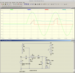
I wonder if it would be worth adding one more diode, and a capacitor across the LED (to make it stay on a bit longer after each clipping event)?
I think this should work (attached). Some experimentation with the capacitor value might be needed to keep the LED on long enough to be an improvement, without slowing down the clip indicator so much that brief clipping might be missed altogether.
-Gnobuddy
Did some breadboarding today.
The high-pass circuit works. Who-hoo! Lovered the value of C13 and C14 to 100nF. That resulted in a bit higher max. cut-off freq, around 300Hz.
Also breadboarded the op-amp clip circuit. Both works, but the 1uF cap across the LED (and its resistor) dont have any visual effect. Only about 100uf and 220uF makes it light up longer, BUT the intensity of the LED is not as bright.
Good idea, but not very practical.
Something way more practical would be to somehow integrate a green "signal" LED to the circuit. I have no idea how to experiment with something like that, so...
One perhaps a very insignificant thing I've been wondering about is the values of R6 and R7 in the gain stage. Are those value critical somehow? They're now set to 10k, but could they be like 1k or even 100k? Does it matter?
Cheers, "Bobby"
Thanks for testing it out. The trouble is that (relatively speaking) it takes a lot of current to charge up a 100 uF capacitor in a millisecond or two, and the TL072 cannot deliver that much current.Good idea, but not very practical.
I think it would work better to have the capacitor working at a smaller signal (current) level, and buffer it to drive the LED, but that would require two opamps.
There's a red/green LED indicator circuit here that might be of interest (I haven't tried it): MUFF WIGGLER :: View topic - [Project] 1 LED signal level meter (sch+PCB)
They're not critical, over a reasonably wide range. Lower values reduce thermal noise a little, but demand more current from the opamp. Extremely high values will misbehave because stray capacitances in the circuit will start to affect impedance, and/or may increase DC offset due to input bias current of the opamp....the values of R6 and R7 in the gain stage. Are those value critical somehow? They're now set to 10k, but could they be like 1k or even 100k? Does it matter?
10k is a very commonly used value here. Big enough to not load the op-amp too much, low enough not to add much thermal noise for most applications.
-Gnobuddy
There's a red/green LED indicator circuit here that might be of interest (I haven't tried it): MUFF WIGGLER :: View topic - [Project] 1 LED signal level meter (sch+PCB)
-Gnobuddy
3 op-amps to feed 2 LEDs? That seems a bit overkill to me, but if that is what it takes...
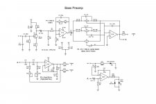
Gonna stick to this original clip circuit. Made a few changes to the overall schematic.
See anything wierd or questionable?
Attachments
For commercial manufacturers, op-amps are dirt-cheap, and you can get four of them in one cheap chip.3 op-amps to feed 2 LEDs? That seems a bit overkill to me, but if that is what it takes...
For us hobby builders, op-amps are still cheap, but now you have all those joints to solder, resistors to install, wires to connect...it gets tedious!
For this reason, one project I will never DIY is an audio mixer. I could use a six-input one, but building six identical channel strips is just too tedious for me. It would probably cost me more than a commercial product by the time I was done, too.
My only suggestion is to breadboard and test that JFET input stage. With the reduced supply voltages that JFETs can handle (compared to old-fashioned vacuum triodes), there is a much finer line between "too clean" and "too distorted".Made a few changes to the overall schematic.
-Gnobuddy
My only suggestion is to breadboard and test that JFET input stage. With the reduced supply voltages that JFETs can handle (compared to old-fashioned vacuum triodes), there is a much finer line between "too clean" and "too distorted".
-Gnobuddy
Allright...
Did some breadboarding on the JFET stage AND some testing at the same time. Had to test out what the minimum (and/or maximum) values for all those caps.
So I decided to remove the cap from source to Gnd. Don't need that much gain. Actually I did test how much gain you can get out of a circuit like this and it seems to be about 10. Fed it with sinuswave 70mV and out came approx. 700mV. Did test out at what point this circuit starts to clip and 800 - 850mV on the output is pretty close, depending on the JFET of course.
So I guess this is what I'm gonna build, working on some layouts.
Cheers, "Bobby"
Attachments
Build finished
Hi guys (and gals).
Thought I just let you know how this project ended up. Just finished the making of the web-page on the project. If you're interested, check it out here:
The Vanguard
Thanks "Gnobuddy", your help was/is much appreciated
Cheers,
"Bobby"
Hi guys (and gals).
Thought I just let you know how this project ended up. Just finished the making of the web-page on the project. If you're interested, check it out here:
The Vanguard
Thanks "Gnobuddy", your help was/is much appreciated
Cheers,
"Bobby"
- Status
- This old topic is closed. If you want to reopen this topic, contact a moderator using the "Report Post" button.
- Home
- Live Sound
- Instruments and Amps
- HELP needed! Bass Preamp Pedal