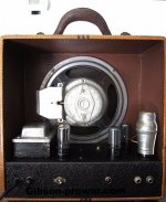
I am looking for a schematic for a 1935-36 Gibson EH150 1st Generation second series amp. I've been asked to bring it back to stock but it came with a 5U4 rectifier, 5V6 and 6V6 power tubes, and a 6A6 preamp tube. I know the 5V6 and 6V6 can't be right and the 5U4 rectifier is a question mark. It looks like the amp was recapped in the 60's and the tech who did it splattered solder all over and did a really bad job. Does anyone know where I could find a schematic? This is a very early amp with no volume control or any pots at all. There is a resistor on the one input jack and a cathode resistor but that is all. There is a choke, a field coil speaker, and a lot of dust. Any help on a schematic would be fantastic!
Attachments
Yes wrong valves!
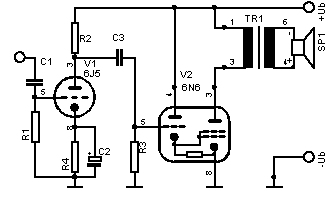
Here is the schematic.
http://archive.gibson.com/Files/schematics/EH-150%20Amp.pdf
Don't forget the standard was not set for multipliers of component values! In this case M means x1000 or k.
Here is the schematic.
http://archive.gibson.com/Files/schematics/EH-150%20Amp.pdf
Don't forget the standard was not set for multipliers of component values! In this case M means x1000 or k.
Last edited:
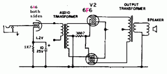
This amp is second version first series from 1936. Here is a quote from VG mag. This amp has no volume control and a 6A6 double triode preamp.
I found this article in Vintage Guitar Magazine and it explains the circuit. What I thought was the OT is a phase inverter. The OT is mounted on the field coil speaker. From VG mag: "Style 1 (1935-’36)
Like all amps of the time, there was no control panel on the chassis of the first E-150s. The power cable, fuse holder (round, house-fuse style on earliest models), on/off switch, pilot light, and two inputs were all secured directly to the backside of the bottom-mounted, bent-metal chassis. A black crinkle paint covered all the exposed surfaces and, like many of the amps of the time, there were no volume or tone controls.
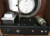
Four tubes were laid out similar to Alvino’s Rickenbacher, to the left between the power transformer and the speaker came either a glass 80 or metal 5Z4 rectifier. Twin 6F6s for the power were mounted catty-corner to the right of the speaker with a shielded 6A6 preamp in the front right corner. This triode (actually twin triodes in parallel for Class A operation, as specified in the RCA tube manual) was fed directly by the parallel inputs and was all she wrote in the preamp tube gain department (amplification factor of approximately 35, compared to 100 for the modern 12AX7). The paralleled plates in turn directly fed the phase inverter, with no need for coupling caps.
Like many amps of the era, phase inversion for the push/pull outputs was performed by a transformer of the center-tapped secondary type, which stepped up the voltage negligibly while providing equal but opposite signal to the power tubes.
This device was mounted to the back wall of the chassis (opposite the inputs), as were the power supply filter caps (two large boxes). Between the front and back panels were the tube sockets, with only a few resistors and caps professionally connected using binding posts, a large grounding strip, and neatly tied wires. Whoever was building these – and it wasn’t the Gibson factory – knew proper assembly techniques (and could have taught Leo Fender a thing or two in his early days).
Access to the interior is a breeze, with the chassis secured to the cabinet by a single large bolt from underneath protruding through the metal topside before being capped by a fancy brass nut. Alligator cloth/paper lined the insides of the tweed-covered cabinet as neatly as plaid would line a suitcase of the era, a very pleasing touch. A small label attached to the inside surface of the removable back cover (also lined) had the serial number pencilled in. This number also shows up inside the chassis and on the magnet cover of the speaker. Utah’s respected 10″ field coil model, previously used by Rickenbacher, was standard."
I found this article in Vintage Guitar Magazine and it explains the circuit. What I thought was the OT is a phase inverter. The OT is mounted on the field coil speaker. From VG mag: "Style 1 (1935-’36)
Like all amps of the time, there was no control panel on the chassis of the first E-150s. The power cable, fuse holder (round, house-fuse style on earliest models), on/off switch, pilot light, and two inputs were all secured directly to the backside of the bottom-mounted, bent-metal chassis. A black crinkle paint covered all the exposed surfaces and, like many of the amps of the time, there were no volume or tone controls.
Four tubes were laid out similar to Alvino’s Rickenbacher, to the left between the power transformer and the speaker came either a glass 80 or metal 5Z4 rectifier. Twin 6F6s for the power were mounted catty-corner to the right of the speaker with a shielded 6A6 preamp in the front right corner. This triode (actually twin triodes in parallel for Class A operation, as specified in the RCA tube manual) was fed directly by the parallel inputs and was all she wrote in the preamp tube gain department (amplification factor of approximately 35, compared to 100 for the modern 12AX7). The paralleled plates in turn directly fed the phase inverter, with no need for coupling caps.
Like many amps of the era, phase inversion for the push/pull outputs was performed by a transformer of the center-tapped secondary type, which stepped up the voltage negligibly while providing equal but opposite signal to the power tubes.
This device was mounted to the back wall of the chassis (opposite the inputs), as were the power supply filter caps (two large boxes). Between the front and back panels were the tube sockets, with only a few resistors and caps professionally connected using binding posts, a large grounding strip, and neatly tied wires. Whoever was building these – and it wasn’t the Gibson factory – knew proper assembly techniques (and could have taught Leo Fender a thing or two in his early days).
Access to the interior is a breeze, with the chassis secured to the cabinet by a single large bolt from underneath protruding through the metal topside before being capped by a fancy brass nut. Alligator cloth/paper lined the insides of the tweed-covered cabinet as neatly as plaid would line a suitcase of the era, a very pleasing touch. A small label attached to the inside surface of the removable back cover (also lined) had the serial number pencilled in. This number also shows up inside the chassis and on the magnet cover of the speaker. Utah’s respected 10″ field coil model, previously used by Rickenbacher, was standard."
6A6 pre amp, 6F6 x 2 for power out and a rectifier.
Nice and simple.
Yes, very few caps, none in fact except for the filters and some type of cap on the 6A6. The one installed in the amp is installed on pin 4 the cathode and is a 10mf/450v with the + to ground. Can that be correct?
The other filters are a 20mf and 2-40mf. There is also a transformer used for the phase inverter!
I wish I could find a schematic because I'm uncertain about the layout since it was so badly cobbled up. I've pulled out a handful of solder globs that were laying around in the chassis and across the pins of one power tube!
The physical layout is in the text you quote. The electronic design is simple. 6A6 drives an interstage which flogs a 6F6 team.
Key questions: are the field coil speaker and the interstage transformer in good working order? They can be replaced but not with original parts.
The 6A6 probably has a 900r-1K cathode resistor and little else. The 6F6es share a 320r cathode resistor, and may have a 2K screen resistor (or may eat full B+).
Input sensitivity may be over 0.5V, which will be "hard work" for modern guitarists accustomed to 0.020V sensitivity. (Distortion was still considered rude.)
The schematic says 6N6 for outputs.
6N6G - Triode, Amplifier | Antique Electronic Supply
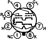
6N6, Tube 6N6; Rohre 6N6 ID9221, MULTI-SYSTEM, internal coup
https://frank.pocnet.net/sheets/201/6/6N6MG.pdf
https://frank.pocnet.net/sheets/201/6/6N6.pdf
https://frank.pocnet.net/sheets/049/6/6N6G.pdf
https://frank.pocnet.net/sheets/084/6/6N6G.pdf
https://frank.pocnet.net/sheets/127/6/6N6G.pdf
6N6G - Triode, Amplifier | Antique Electronic Supply
By coincidence, I'm working on a Silvertone 4590 which also uses 6N6 tubes. According to the 1946 Sylvania tube manual, the 6N6 is a dual triode with direct coupling from one section to the other, and is the octal equivalent of the 6B5. It is designed to run without any bias, so a 6V6 or 6K6 would probably work if you lifted the cathode from ground and used the correct cathode resistor and a 20 mfd bypass capacitor. Use a 270 ohm 1 watt for the 6V6, and a 470 ohm 1 watt for the 6K6. The 6N6 should still be available from AES, Radio Daze
I remember making a similar substitute of a 41 for a drop-in replacement for a 6B5 in an Aetna console some years ago. I was pleasantly surprised how nice it sounded. One would probably need the assistance of a friend to do an unbiased test, though.
A 6AB6G is listed as a sub for the 6N6G in the tube search I use.
The 6AB6G and 6N6G share the same base diagram, and could well be interchangeable.
6N6, Tube 6N6; Rohre 6N6 ID9221, MULTI-SYSTEM, internal coup
https://frank.pocnet.net/sheets/201/6/6N6MG.pdf
https://frank.pocnet.net/sheets/201/6/6N6.pdf
https://frank.pocnet.net/sheets/049/6/6N6G.pdf
https://frank.pocnet.net/sheets/084/6/6N6G.pdf
https://frank.pocnet.net/sheets/127/6/6N6G.pdf
The physical layout is in the text you quote. The electronic design is simple. 6A6 drives an interstage which flogs a 6F6 team.
Key questions: are the field coil speaker and the interstage transformer in good working order? They can be replaced but not with original parts.
The 6A6 probably has a 900r-1K cathode resistor and little else. The 6F6es share a 320r cathode resistor, and may have a 2K screen resistor (or may eat full B+).
Input sensitivity may be over 0.5V, which will be "hard work" for modern guitarists accustomed to 0.020V sensitivity. (Distortion was still considered rude.)
PRR, thanks for the thoughtful response! I've used a 1K 2W resistor on the cathodes of the 6A6 and bypassed the resistor using a 50V 10mf cap. My concern now is the pair of 6F6's and the voltage they are receiving. I'm measuring 287V on the plates (pin 3) of the 6F6's and 295V on the screen (pin 4). I have a 200 ohm cathode resistor on the 6F6's that I've also bypassed with a 50V 25mf cap.
The screen voltage seems a little high so I probably should install a 470 Ohm resistor on the screens?
The field coil speaker does work as does the phase inverter transformer and signal is passed to speaker. There is a crackling noise that is constant but faint and I've used a chopstick to try and find a bad connection to no avail. Possibly a bad tube?
I'm getting close to getting things sorted!
I'm not worried about that screen voltage. Anyway 12mA in 470r is no drop at all.
I would be more interested in cathode voltage, so we know the cathode current, and thus the plate dissipation. 200r seems wrong, and I see no point in cooking 6F6es.
Okay, I won't worry about the screens!
The cathode voltage is 17V with the 200r
Here is the differences;
The 6N6 is a heater type output tube comprising two triode units mounted in a common bulb. The smaller (or input) section acts as driver for the larger output unit and is directly coupled to it. The input cathode and output grid are connected internally. The tube operates without bias so there is no need for a cathode resistor and it's associated by-pass condenser.
Since the output section operates with a positive bias, it requires a high-mµ characteristic to keep the plate current low. This is achieved by using two separate control grids connected in parallel inside the bulb.
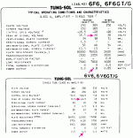
Type 6F6 is a general-purpose audio output pentode intended for domestic and car radios. It dates from the mid-1930s and was a well-established classic long before WWII. Its output is roughly similar to that of the well-known type 6V6 but it was considerably more sensitive and could be driven directly from the detector output, thus saving one stage of audio amplification. This was convenient particularly in compact car radios but the price of the extra gain was paid in a larger cathode and more heater power than the 6V6. As a result it tended to run hot and, in car radios, a derating was normally recommended.
The operating values given are for single ended use with an anode load of 7,000 Ohms.
If a pair are used as an audio amplifier in push pull class A, 10.5 Watts are possible with 3% distortion.
The equivalent type KT63 is a beam tetrode. Electrically identical types but on UX6 bases are the Type 42 with a 6.3 Volt heater and 2A5 with a 2.5 volt heater.
The 6N6 is a heater type output tube comprising two triode units mounted in a common bulb. The smaller (or input) section acts as driver for the larger output unit and is directly coupled to it. The input cathode and output grid are connected internally. The tube operates without bias so there is no need for a cathode resistor and it's associated by-pass condenser.
Since the output section operates with a positive bias, it requires a high-mµ characteristic to keep the plate current low. This is achieved by using two separate control grids connected in parallel inside the bulb.
Type 6F6 is a general-purpose audio output pentode intended for domestic and car radios. It dates from the mid-1930s and was a well-established classic long before WWII. Its output is roughly similar to that of the well-known type 6V6 but it was considerably more sensitive and could be driven directly from the detector output, thus saving one stage of audio amplification. This was convenient particularly in compact car radios but the price of the extra gain was paid in a larger cathode and more heater power than the 6V6. As a result it tended to run hot and, in car radios, a derating was normally recommended.
The operating values given are for single ended use with an anode load of 7,000 Ohms.
If a pair are used as an audio amplifier in push pull class A, 10.5 Watts are possible with 3% distortion.
The equivalent type KT63 is a beam tetrode. Electrically identical types but on UX6 bases are the Type 42 with a 6.3 Volt heater and 2A5 with a 2.5 volt heater.
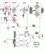
So I am missing something? Is the schematic representative of the amp or is there another we are following? 6F6 is not a 6N6. I have nothing against 6F6's as I have two pair I want to use eventually. I am just confused.
I am confused too.
The OP says he has the interstage which would indicate the first schematic and 6N6's. But goes on to say he has the second iteration of the amp which has a paraphase splitter AC coupled to 6L6's

There is a "Plan B" possible: since the amp has already been poorly modded (to put it mildly), you can just strip it ,leaving a naked chassis, iron and sockets, (in any case caps must go after all these years and tubes are wrong) and plain rebuild from scratch, following any 1936 vintage *original* Gibson schematic.
You can trust that way more than anything you found there and will definitely be more "like the original".
IF the speaker needs reconing, contact Ted Weber (his Son actually) to lovingly rebuild it the old way, any other reconer will just slap modern parts using modern adhesives into it and call it a day.
As of "Guitar players having to strum hard" .... consider that until pickups and amps appeared , Jazz players had been playing their big box Jazz Guitars **unamplified** and in a Jazz Band environment ... talk about strong fingers")
You can trust that way more than anything you found there and will definitely be more "like the original".
IF the speaker needs reconing, contact Ted Weber (his Son actually) to lovingly rebuild it the old way, any other reconer will just slap modern parts using modern adhesives into it and call it a day.
As of "Guitar players having to strum hard" .... consider that until pickups and amps appeared , Jazz players had been playing their big box Jazz Guitars **unamplified** and in a Jazz Band environment ... talk about strong fingers
Last edited:
So I am missing something?...
Yes.
First: at Gibson, "EH150" meant as much as Ford's "Mustang" or Buick's "Special": badges that got applied to MANY different products.
Second: e-guitar was JUST starting; so were LOUDspeaker radios (from which g-amps got their parts). There was a fad for Hawaiian guitar, which was OK on a quiet beach but not in a drinking house. The amplifier brought the tiny-body sound up to near the level that an acoustic big-body band guitar could do. That was a start but soon players wanted much more gain. Also the fashionable/cheap power tubes changed every other year. So there's at least three quite different "EH150" in the 1930s. The plan in post #2 above is apparently not David's.
Please re-read post #3, which David says appears to be what he has.
"...either a glass 80 or metal 5Z4 rectifier. Twin 6F6s for the power were mounted catty-corner to the right of the speaker with a shielded 6A6 preamp in the front right corner. This triode (actually twin triodes in parallel for Class A operation, as specified in the RCA tube manual) was fed directly by the parallel inputs and was all she wrote in the preamp tube gain department.... The paralleled plates in turn directly fed the phase inverter, .... performed by a transformer of the center-tapped secondary type, which stepped up the voltage negligibly while providing equal but opposite signal to the power tubes."
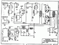
That's my hack-up showing 6F6 finals. I'll include a couple later "EH-150"s that added another gain stage for instruments, but two different final tubes. (6N6 is indeed an oddity.)
Attachments
David: does your tube shield say "Goat"?
That looks like 11 Watts in an 11W plate. I'd fret; except with Field Coil speaker the speaker sensitivity and damping changes with amplifier total power demand. As I do not think this will be a 40 hour a week amp, I'd leave it as it is.
I think it can only be a curiosity, or special-sound, amp, not something any modern player would use a lot. Gain is way low, apparently low even within a few years. We could "fix that" with another stage or a booster pedal. But that speaker was only strong enough to play clean (like a radio), not to survive OVERdrive. And hasn't gotten any stronger in 80 years.
...The cathode voltage is 17V with the 200r
That looks like 11 Watts in an 11W plate. I'd fret; except with Field Coil speaker the speaker sensitivity and damping changes with amplifier total power demand. As I do not think this will be a 40 hour a week amp, I'd leave it as it is.
I think it can only be a curiosity, or special-sound, amp, not something any modern player would use a lot. Gain is way low, apparently low even within a few years. We could "fix that" with another stage or a booster pedal. But that speaker was only strong enough to play clean (like a radio), not to survive OVERdrive. And hasn't gotten any stronger in 80 years.
....Type 6F6 is a general-purpose audio output pentode..... roughly similar to ...6V6 but it was considerably more sensitive and could be driven directly from the detector output, thus saving one stage of audio amplification.
You don't cite a source but this tidbit is just wrong. 42/6F6 needs ~~1.5X the drive, is noticeably less sensitive than 6V6.
There were European power tubes of high sensitivity to avoid one stage of audio gain. In the US this practice was nearly unknown, unless you got down to 3-tube reflex radios only good for very local stations. In Europe the stations are crowded together and you don't need a lot of gain to make a mess of interference. In the US it was common to pull stations from 900 miles, gain was useful, audio gain is cheap.
Attachments
6N6 source; 6N6, Tube 6N6; Rohre 6N6 ID9221, MULTI-SYSTEM, internal coup
6F6 source; 6F6 @ The Valve Museum
6F6 source; 6F6 @ The Valve Museum
Yes.
I missed that he stated it was the second version, thought he wanted to bring it back to the schematic shown. I think going with 6F6's even if it was a 6N6 amp would be best. Carry on.
Hi All,
Sorry, I just noticed there had been replies to my posts. Yes it is an EH150 with the 6A6 preamp triodes and the 6F6's. My calculations so the tubes to be at 12.4 watts at idle using the 200r resistor. Would it make sense to go with a 250 to 270r resistor to lower the bias of the 6F6? I have the amp running but as it warms up without a guitar plugged it squeals and with an input plugged in the squealing goes away but the amp crackles continually. I've poked around trying to find a cold solder joint to no avail and all the resistors and caps have been replaced so I'm out of ideas. Granted there are only 3 filter caps and one cathode resistor for the pair of 6F6's and a 1K for the 6A6.
PRR, you are correct in that this is going to be used by a friend who has vintage Gibson guitars that he wants to use to play thru the amp! With the original cone on the field coil this amp isn't gonna be pushed very hard!
Thanks everyone for your help!!
Dave
- Home
- Live Sound
- Instruments and Amps
- looking for schematic for prewar Gibson EH150