Dear All it is my first post here, I built a 1000w amplifier and I need to find a suitable clip detector circuit which will indicate on an LED in the front panel. My rail voltage is 80v-0-80v. un-regulated. The circuit I tried previously was lighting up the LED prematurely. I tried to change the bias resistors to suit the higher voltage involved but still I lost sensitivity at high frequencies. (8-10Khz).
I will be very grateful is someone can provide me with a suitable circuit that I can build.
Regards, Silvi.
I will be very grateful is someone can provide me with a suitable circuit that I can build.
Regards, Silvi.
Do you have a schematic of the one you built?
Many indicators are also being fed from the input of the amp.
If you want a "true" indicator you could feed a comparator with the output peak voltage and the supply voltage minus the saturation voltage of the power stage.
Edit: is it really important to show an *exact* clipping point at 10kHz?
Many indicators are also being fed from the input of the amp.
If you want a "true" indicator you could feed a comparator with the output peak voltage and the supply voltage minus the saturation voltage of the power stage.
Edit: is it really important to show an *exact* clipping point at 10kHz?
Last edited:
Thanks for the reply GeorgK
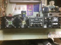
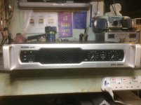
I want to brief you out in what I did. I had an existing commercial amplifier box which had its amp and power supply burnt. I got rid of these and fitted my home made smps and also a new amplifier module.
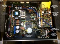
I used the existing preamp and front controls from the old amp but I had to make an interface to combine everything together and I also included a signal indicator with an opamp. I also had to include the clip indicator on a separate board but had to create isolation with an opto coupler not to interfere with the preamp circuit and the low voltage rails. See pics for details.
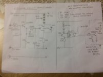
I am also posting a pic with the circuit I used and also included the resistors that I changed to make this circuit work properly with a normal LED but when I included the opto It started to act strangely and lighting up prematurely at 1Khz tone, it also lost response at 8Khz and not lighting up at all when the amp starts clipping. (Tests where made with dummy load 8 Ohms and scope attached across the load resistor).
I want to brief you out in what I did. I had an existing commercial amplifier box which had its amp and power supply burnt. I got rid of these and fitted my home made smps and also a new amplifier module.
I used the existing preamp and front controls from the old amp but I had to make an interface to combine everything together and I also included a signal indicator with an opamp. I also had to include the clip indicator on a separate board but had to create isolation with an opto coupler not to interfere with the preamp circuit and the low voltage rails. See pics for details.
I am also posting a pic with the circuit I used and also included the resistors that I changed to make this circuit work properly with a normal LED but when I included the opto It started to act strangely and lighting up prematurely at 1Khz tone, it also lost response at 8Khz and not lighting up at all when the amp starts clipping. (Tests where made with dummy load 8 Ohms and scope attached across the load resistor).
Attachments
Hi Silvio
The indicator worked without the photo-coupler? Strange enough, but anyway:
I do not really get why you need it. You have a common ground I suppose.
To protect the existing LED control from overvoltage coming from the indicator circuit you probably could add one more transistor and a clamp diode.
The indicator worked without the photo-coupler? Strange enough, but anyway:
I do not really get why you need it. You have a common ground I suppose.
To protect the existing LED control from overvoltage coming from the indicator circuit you probably could add one more transistor and a clamp diode.
Last edited:
Member
Joined 2009
Paid Member
1000W is huge ! - and you're worried about clipping 
I've been looking for a 4W guitar amp schematic for my sister. I can only imagine that clipping a 1kW amp would first be noticeable from the blood pouring out of my head before I'd notice any LEDs flashing
Maybe this is useful: Project 146
I've been looking for a 4W guitar amp schematic for my sister. I can only imagine that clipping a 1kW amp would first be noticeable from the blood pouring out of my head before I'd notice any LEDs flashing
Maybe this is useful: Project 146
1000W is huge ! - and you're worried about clipping
I've been looking for a 4W guitar amp schematic for my sister. I can only imagine that clipping a 1kW amp would first be noticeable from the blood pouring out of my head before I'd notice any LEDs flashing
Maybe this is useful: Project 146
Thanks very much for the link I also was considering this project but it seems that your link is more detailed than the one found on line.
I will try to play a bit more with the existing circuit that I have and if I am not successful I will try this one.
You can measure the current at the output.
If I had to measure the current on the output I am not sure if this will be correct all the time if I had to change speaker impedance from 8 to 4 ohms for example.
New settings have to be made in that case. The supply is not regulated and at 4 ohms the current will be larger and the rail voltage will sag more with load. It could be that a different current and voltage rating will ensue. Clipping will occur on a different current hence measuring the rail voltage against the voltage swing on the output of the amp will give a more accurate reading I guess.
- Home
- Live Sound
- Instruments and Amps
- Clip detector and indicator for 1000w amp