Now, back to load resistance for tubes in AB1 push-pull operation: Datasheet for 6V6 tubes in this mode state 8000Ω plate-to-plate load resistance; DR transformer is 6600Ω. Same discrepancy found in Pro Reverb: two 6L6s in AB1, datasheet says 5600Ω, transformer used is 4000Ω. Why is this?
Here, I can only make what I think is a good guess.Now, back to load resistance for tubes in AB1 push-pull operation: Datasheet for 6V6 tubes in this mode state 8000Ω plate-to-plate load resistance; DR transformer is 6600Ω.
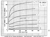
The datasheet curves (attached) are for 285V on the screen grid (G2). With this voltage on G2, notice that anode current never really rises above 110 mA, even with 400 volts on the anode (and zero grid bias, zero volts on the control grid, G1.) Operated within factory specs, with control grid never going positive, you cannot squeeze more than 110 mA out of a 6V6.
We found out in the earlier calculations that you need something like 270 volt peak voltage across each half of the Deluxe OT primary to deliver 22 W to the speaker.
Ohm's law tells us that if we apply 270 volts to 1650 ohms (anode to centre-tap primary impedance), 163.6 mA of current must flow.
And we just found out that according to the manufacturer's datasheet, a 6V6 cannot deliver 163.6 mA, even with 400 volts on the anode, and zero volts on the control grid!
So now we have another connundrum: operated within factory specs, with control grid never going positive, you cannot get a 6V6 to drop 270 volts across a 1650 ohm load. So a pair cannot deliver 22 W into a 6600 ohm OT primary.
So how did Leo manage it? He didn't put 285 volts on the screen grid, he put something closer to 400 volts on them. Increasing G2 voltage has the effect of lifting all the anode current curves higher.
Without measuring one with a curve-tracer, I can't say exactly how much higher the 6V6 curves go with 400 volts on G2. But we must assume that the former 110 mA curve has risen to something well over 163.6 mA. Otherwise, there is no way to get that required 270 V peak voltage, and no way to drive 22 W into the speaker.
So now we know the factory datasheet curves are worthless in Leo's world, a world in which you penny-pinch the cheapest output valve you can find till the anode glows dull red, rather than do the right thing and buy the next size bigger valves.
In Leo's penny-pinching world, the 6V6 curves have all moved far from where the factory told you to expect to find them.
With all the curves moved, the factory load-line doesn't apply, either. With all the curves moving higher (more current at the same anode voltage), you will now need a lower-resistance load.
How much lower? Again, we can't tell without actually measuring 6V6 curves with 400V on G2. But apparently, Leo found that OT's with a 6600 ohm primary did the trick.
Whether Leo did careful testing to find the optimum, or simply bought the cheapest OT he could find that was "a bit less than 8000 ohms", we can only guess. My bet is that it was the latter.
So the short answer to your question is: if you operate the valves far, far, far from factory specs, then the proper load impedance will also be far from the factory specs.
-Gnobuddy
Attachments
The 1937 suggestions for the 6V6 are very conservative. The idea was to replace 6F6 with essentially the same parts, lower grid drive, lower heater power, and about the same output. These suggestions were never changed; perhaps to avoid eating sales of other less-generic types.
Just scaling B+ from 285V to 400V suggests double the power. 22W makes perfect sense.
Voltage goes about as B+ but current increases more like 3/2 Power Law. Double voltage makes 2.8X current, which suggests 0.7X load impedance. We can't normally double B+, and we should respect Pdiss, but it is reasonable to shift from 8K to 6.6K.
If anybody is still unclear how we have >1000V p-p with only 400V supply....
Draw it out with 1-thumb numbers so the arithmetic is clear.
We have 400V. The tube will pull-down imperfectly, say to 100V. A 300V down-swing. It will also kick-up the same amount, to 700V. So 600V p-p on one side. On the other side it swings up to 700V and down to 100V. Totals as shown.
Draw it out with 1-thumb numbers so the arithmetic is clear.
We have 400V. The tube will pull-down imperfectly, say to 100V. A 300V down-swing. It will also kick-up the same amount, to 700V. So 600V p-p on one side. On the other side it swings up to 700V and down to 100V. Totals as shown.
Attachments
Last edited:
So much for my envelope...Note the factor of 8 in the denominator: this comes from the conversion of peak-to-peak voltage to RMS voltage [divide by 2 times the square root of (2)], and then squaring that to get RMS voltage squared. Squaring [2 x root(2)] gives you exactly 8.
 I used peak voltage instead of RMS voltage for the calculation, some one should check the checker! Thanks for your patience and taking the time to explain everything.
I've had a few of those defective envelopes in my hands over the years, too.So much for my envelope...
And you're quite welcome, glad I could help!
-Gnobuddy
Are there any 6V6 datasheets that shows plate curves at various different G2 voltages? That might let us extrapolate roughly where the 400V G2 lines fall, at least the G1=0 line....current increases more like 3/2 Power Law.
I forgot something when I said earlier that the line would have to move up to at least ~164 mA. There should be something like 20 mA quiescent current on top of that, so the line really needs to move somewhere above 185 mA at a minimum.
Tubelab George's approach of driving G1 into positive grid voltage territory - but with only 250V on G2 - makes more sense to me than Leo's sky-high voltage on everything.
Not that Leo could have taken that approach, though. He didn't have modern power MOSFETs to drive the control grids with.
-Gnobuddy
Datasheet for 6V6 tubes in this mode state 8000Ω plate-to-plate load resistance; DR transformer is 6600Ω. Same discrepancy found in Pro Reverb: two 6L6s in AB1, datasheet says 5600Ω, transformer used is 4000Ω. Why is this?
Simple explanation from the economics view. The values published in the tube manual come from the company covering the warantee on the tubes. The values used by Fender and others come from the people who refer to tubes as consumables.
Yes I have squeezed 35 watts from a pair of 6V6 tubes with a 3300 ohm OPT and relatively sane B+ and screen voltages. The plate dissipation is only exceeded by a watt or three (depending on which data book you read) on music peaks which don't come too often in a HiFi amp (the application I am working on).
A guitar amp typically drives a speaker which has its resonant impedance peak within the guitar's frequency range. The true impedance of an "8 ohm" speaker in the region near resonance is in the 15 to 40 ohm range. Often a lower impedance OPT can sound louder, since it is seeing a much higher load impedance over a good portion of a guitar's fundamental frequency range.
If anybody is still unclear how we have >1000V p-p with only 400V supply....
The key point is that the transformer operates on current. That's what makes the magnetic fields that do all the work.
So we can start at the load and the wattage to calculate a current flow. Then we can calculate the current flowing in the primary (assuming no losses). Now we can figure out the voltages necessary on the primary, realizing that the tube is very much a valve allowing current to flow.
Ergo, the voltage on the primary is a byproduct not a cause. Vpp therefore is not some kind of limitation to primary voltage.
...transformer operates on current.....
All power systems operate on both voltage and current, sure.
An ideal transformer, no load, draws no current.
Mid-band, a $50 transformer draws very-little current above load current. (Yes, the bass sucks current.)
Assuming the 6V6es swing voltages leads to the only possible answers. I'm not sure your "operates on current" insight adds anything.
It is however perhaps important to use a large enough "envelope" to sketch the WHOLE circuit and annotate all numbers as peak or peak-peak, etc. There's too many loose ends to keep all straight in the head or on a matchbook.
The reason for my comment, hopefully to add insight to the person asking the question, is that people tend to look at the power supply voltage as defining the limits of what will be found within the circuit. Modern semiconductor circuits would normally stay within those voltage boundaries.
Are there any 6V6 datasheets that shows plate curves at various different G2 voltages?
Ponder the Triode curves. You know the plate current is hardly affected by plate current. The rise of total current is due to higher voltage on G2.
You can also ponder 7027 sheets, some of which show Vg1 curves for several Vg2 values.
...driving G1 into positive grid voltage territory - but with only 250V on G2 - makes more sense to me than Leo's sky-high voltage on everything.
Positive grid means a POWER driver. The asymmetry means cap-coupling will just grid-block, forcing transformer or followers. The mild grid-block possible (and controllable) in nominal neg-grid cap-coupled overdrive turned out to be very musically useful (see Neil Young).
And tubes LOVE voltage. Vacuum is a terrible conductor. Voltage urges the little electrons along. Yes, high voltage is hard on materials. The 315-350 spec on 6V6 is probably about allowing use of the cheapest plate-metal (or softest oxides) to keep cost down. And when 6V6 was new, nobody had much over 300V in hand. Electrolytic caps don't like >450V, usually run less, and then the Field Coil used 100V-150V. So 300V rating was ample. But as these mild-mannered radios vanished, and hard-worked TV sets dominated, the factories had improved materials in bulk.
If you can put your incessant Leo-bashing aside for a moment, don't you suppose that maybe the 6V6 with 415v and a 6600Ω load just sounded better? Leo listened to musician's input probably better and more often than did any other manufacturer.So how did Leo manage it? He didn't put 285 volts on the screen grid, he put something closer to 400 volts on them. .....So now we know the factory datasheet curves are worthless in Leo's world, a world in which you penny-pinch the cheapest output valve you can find till the anode glows dull red, rather than do the right thing and buy the next size bigger valves. In Leo's penny-pinching world, the 6V6 curves have all moved far from where the factory told you to expect to find them. .....How much lower? Again, we can't tell without actually measuring 6V6 curves with 400V on G2. But apparently, Leo found that OT's with a 6600 ohm primary did the trick. Whether Leo did careful testing to find the optimum, or simply bought the cheapest OT he could find that was "a bit less than 8000 ohms", we can only guess. My bet is that it was the latter.
Sigh. I'm not interested in bashing Leonidas. I'm also not interested in worshipping him through rose-coloured glasses.If you can put your incessant Leo-bashing aside for a moment
I am somewhat interested in understanding some of the technical decisions he made. Sixty or seventy years later, the cult of Leo tends to blindly see these as always superior, but let's not forget they were often despised by contemporary instrument manufacturers who saw them as cheap and shoddy shortcuts.
No, I don't think so, for a few reasons. The most compelling one: put a VVR on a pair of 6V6s and try changing the B+, and listening.don't you suppose that maybe the 6V6 with 415v and a 6600Ω load just sounded better?
For clean guitar tones - the only kind Leo was interested in - I've found negligible difference in output stage tone over a wide B+ range, most particularly in push-pull output stages, as long as you're not pushing the amp to near its full limits.
Also interestingly, I have two Fender amps with virtually identical power amp sections, both using 6V6 outputs. The Superchamp XD has lower B+ than the Princeton Reverb reissue. And the XD has considerably better clean tone!
I don't think the lower B+ is responsible for the better tone, except indirectly: the 445V B+ in the PRRI more or less mandates the use of JJ 6V6S outputs, which seem to be clean to the point of sterility. So here is a case or more B+ indirectly creating worse clean tone.
When I stand back and look closely at Leo's creations, they always seem to fit the mould of accountant-thinking: the cheapest-made thing that the customer will buy without too much complaint. Essentially the Walmart approach to product design.
Worth noting: the most iconic Fender product - the Stratocaster - was created mostly by Freddy Tavares, after Leo told him he wasn't interested in Tavare's ideas for a new guitar. Leo did let Tavares work for him, for free, while Tavares worked out the design and built some prototype guitars, though.
Without Tavares, Jimi probably wouldn't have played a Fender guitar, and the striking shape of the 'Strat wouldn't have inspired a million kids to learn to play the electric guitar. Without Jimi, Fender Corporations fortunes would probably have taken quite a different turn.
Since the discussion of 6V6 load lines is essentially at an end, and we are now on subjective ground where there is rarely any agreement or useful outcome, I will now tip my hat to all of you, wish you a good day, and depart this thread.
-Gnobuddy
- Status
- This old topic is closed. If you want to reopen this topic, contact a moderator using the "Report Post" button.
- Home
- Live Sound
- Instruments and Amps
- 6V6 load resistance