Hi all,
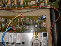
I recently acquired a Gallien Krueger RB400 (schematic / service manual here) which has a few burnt components on the power supply board (see attached image). R28 looks especially toasty. Which components should I replace before powering up? Is the fault likely a bad output transistor (Q11)?
Any help is greatly appreciated.
Attachments
This is the power amp, not the supply.
What are the symptoms? Does it blow a fuse? Or is it just not working?
I would especially suspect the output transistors, probably all. (Q8,9,11,12) Take them out and check them for shortings. Also the drivers could be damaged. The way the PCB looks like, you may also find burnt traces. In fact you should check every semiconductor, plus the resistors, also the "big" emitter resistors. (Actually, do not leave any component). Damage may be bigger than it looks.
To be honest, this may turn out to a work for an experienced technician, also the amp will probably require bias adjustment afterwards.
Last edited:
R28 is what turns on the over current protection. Probably cooked by an output transistor fault or the bias set pot failed which caused the output transistors to cook which then fried a bunch of other components. You'll have to check every thing after and including the bias set circuit.
Ok, thanks guys. I got the amp for free so I'd like to use it as a learning tool. I have an engineering background, but not EE, so please bear with my beginner questions.
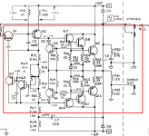
Attached is the likely problem area, correct? Is it possible to test the transistors in circuit?
If not I'll remove Q1-Q12 and test. If I need new parts, is there a preferred vendor? Mouser, Digikey?
Attached is the likely problem area, correct? Is it possible to test the transistors in circuit?
If not I'll remove Q1-Q12 and test. If I need new parts, is there a preferred vendor? Mouser, Digikey?
Attachments
Those suppliers are fine, I use them.
test them in circuit first, if any seem shorted, pull them and test them. I am not a fan of wholesale parts removal and replacement, it adds more opportunities to screw up. If a part shows shorted, we need to test it, but there is nothing in a circuit that can make a shorted part appear not to be.
Thre are not that many transistors, I would check them all for junction drops where they sit, at least at first. Be aware that in various places there are parallel resistances that affect your readings. For example, Q8, Q9 have 492 ohms across their B-E junction. And Q3 E-C has a Q4 B-C in parallel.
If R28 burnt, then Q5 is suspect, but more than that, R28 had to become a current path, and I then worry that R24 may have opened due to a Q8 short.
Whenever you have to replace power transistors, always verify all the associated resistors, they often burn open.
If you replace an output, I'd replace the driver too, even if it checks good. The failed output could have stressed the driver, and for a dollar it is false economy to ignore that possibility.
The power transistors are especialky difficult to test in circuit, as their emitters are near shorted by their 0R33 resistors. So I would at least take these out. Removing all would be even better.Ok, thanks guys. I got the amp for free so I'd like to use it as a learning tool. I have an engineering background, but not EE, so please bear with my beginner questions.
Attached is the likely problem area, correct? Is it possible to test the transistors in circuit?
If not I'll remove Q1-Q12 and test. If I need new parts, is there a preferred vendor? Mouser, Digikey?
How would you test the transistors? Of course you can have a look at the BE/BC diodes with a multimeter set to diode test, anyway this will give you only a clue when the transistor is competely defective (e.g. shorted diodes).
As you probably have shorted power transistors, replace them all as soon as you find only one shorted. While they are removed, measure all resistors. Replace each one that looks burned. If you find a resistor that measures out of its nominal value, check if this makes sense in the circuit or desolder one side and measure again.
I can only state again that the failure may be complex and that several components may be involved. On way to go could even be to replace all semiconductors in the area in question. Plus all resistors that show the slightest signs of damage.
One thing I would like to add: I have been doing similar repairs for 25 years now. The moment when powering the amp up again time is still a moment of fear. I had more than one that blew again completely, immediately or even after some time during a load test. And I have a variac, a signal generator and a scope for this.
Do not forget to set bias to minimum before.
I would not be too critical about the parts source. You probably cannot go wrong with Mouser or Digikey
Good luck!
Q7 and Q 10.Forgive my ignorance, but how do I identify check a driver? Is there a driver for each transistor, or just for the output transistors?
Tested a few semiconductors in circuit with the following results, positive lead on DMM hooked to first leg listed:
Q11, Mj15002 PNP
1. Base to Emitter: 0.35 VDC
2. Base to Collector: 0.00 VDC
3. Emitter to Base: 0.35 VDC
4. Collector to Base: 0.00 VDC
5. Collector to Emitter: 0.35 VDC
Q3, MPSA06 NPN
1. Base to Emitter: 0.21 VDC
2. Base to Collector: 0.21 VDC
3. Emitter to Base: 0.25 VDC
4. Collector to Base: 0.25 VDC
5. Collector to Emitter: 0.00 VDC
Q4, MPSA56 PNP
1. Base to Emitter: 0.75 VDC
2. Base to Collector: 0.00 VDC
3. Emitter to Base: .84 VDC
4. Collector to Base: 0.00 VDC
5. Collector to Emitter: 0.75 VDC
Q5, MPSA06 NPN
1. Base to Emitter: 0.34 VDC
2. Base to Collector: 0.04 VDC
3. Emitter to Base: 0.34 VDC
4. Collector to Base: 0.04 VDC
5. Collector to Emitter: 0.37 VDC
Q6, MPSA56 PNP
1. Base to Emitter: 0.25 VDC
2. Base to Collector: open circuit
3. Emitter to Base: 0.25 VDC
4. Collector to Base: 0.59 VDC
5. Collector to Emitter: 0.59 VDC
Q10, MJE15031 (PNP)
1. Base to Emitter: 0.00 VDC
2. Base to Collector: 0.00 VDC
3. Emitter to Base: 0.00 VDC
4. Collector to Base: 0.00 VDC
5. Collector to Emitter: 0.00 VDC
Looking at these results, I think my best option is to replace all the semiconductors (Q1-Q16). As Enzo mentioned, the incremental cost is basically zero. I'll test the resistors in this section while I have the semiconductors removed and replace any which are out of spec.
Wait for Enzo´s answer, but I remember he usually stocks "the beefiest transistor in that class" for the very good reasons that price difference from strongest to weakest is about 1 U$ and the beefiest can replace all weaker ones, so .......
I think it was one of the MJ1502x but again, wait for him.
In any case, try to buy from Mouser or Digikey, depending on where you live Farnell might be an option.
EBay is a poker game at the sleaziest joint in town, *sometimes* you win, most often you lose.
I wouldn´t gamble with that amp repair.
***Build a lamp bulb limiter*** and always plug the amp in it, no speaker or any load yet, until all voltages check right.
Also get mica and grease for the transistors, you shouldn´t reuse the old one.
Again, no gambling.
Yes, leave it there and order real parts. NTE are approximations at best and are NOT matches for the other transistors inside the amp. Notice also teh NTE costs $11 while teh MJ15004 costs $4.
Yes, MJ15004 is a perfect sub for the MJ15002.
Yes, I would use MJ15025 myself, but if you are ordering parts, might as well use the close one.
I have four Michelin radials on my car. If I had to replace one, I would want another Michelin radial. That NTE would be like putting on one bias ply snow tire.
Gah looks like the MJ15004 is on backorder (24 week lead time???), so MJ15025s it is.
Try Farnell, at least for Europe they are available there.
If you have set your DMM to diode test mode, your measurements indicate taht all these transistors are faulty. In this case I'd check the remaining ones also.
Yes, as others said, MJ15004 is a good replacement for MJ 15002. Both share their electrical characteristics, but the xx4 withstands higher Vcb and Vce voltages. The MJ15024 is even beefier and faster and will also fit. Another option would be the MJ21194, same data as MJ15024, but extended SOAR due to it's Perforated Emitter Technology.
Best regards!
Yes, I will be replacing all the transistors in the amp. Luckily there are only a handful. I will be sure to retest each transistor once it is removed from the circuit (and test the new transistors prior to installation). If the results don't make sense, I may have to find another DMM!
- Home
- Live Sound
- Instruments and Amps
- Replacing Burnt Components on Gallien Krueger RB400 Bass Amp