I ordered some 6aL5 and 6L6 tubes for a compressor prototype build.
Here is the patent link. https://patentimages.storage.googleapis.com/pdfs/US2849546.pdf
It does not use any integrators etc. Operates in 4 quadrents ‘real-time’.
So we will see if the claims are true.
-
Here is the patent link. https://patentimages.storage.googleapis.com/pdfs/US2849546.pdf
It does not use any integrators etc. Operates in 4 quadrents ‘real-time’.
So we will see if the claims are true.
-
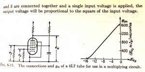
Patent shows 6L7, pentagrid; not 6L6 power tube.
I'd call it 2 quadrant. (4-Q allows inversion which we do not need.)
I can't see how it is more than an elaborate diode-limiter. Yes, it shifts the gain-control function onto an amplifier tube, but without any time-constants it is equivalent to a clipper.
I have real doubt that there is an optimum point for G3 where deviation *either* way reduces gain even approximately equally. That might be the first point to check. When G3 goes low it cuts-off plate current. Maybe when G3 goes high it steals current from plate. I can't see the two effects being equal? And that is not what I am seeing on 6L7 data, for the bias points cited in the patent.
Attachments
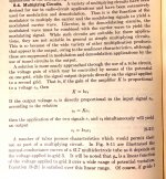
Yes 6L7 typo, here is a paragraph from Seely. G3 is under control for 360 degrees. There is no knee on the 6AL5 like semi's, the diodes are biased on, so no hard clip point. G3 control is quite linear as seen in pic.
No time constant = real-time which is interesting vs integrator
-
No time constant = real-time which is interesting vs integrator
-
Attachments
I tried something like this for use in a music synthesizer. I separated the rectifier and the VCA (voltage controlled amplifier). I did not try the 6L7 but there are more modern equivalents like the very common 6BE6 and somewhat common 6BA7. I had better luck with "dual control pentodes" like the 6AS6. I never took the time to make it all work since the big picture needs a voltage controlled Moog style ladder filter. That's what I need to get working first.
In case it's needed the 6JU8 is two 6AL5's in a single 9 pin bottle. It's on the dollar menu too.
In case it's needed the 6JU8 is two 6AL5's in a single 9 pin bottle. It's on the dollar menu too.
Patent drawings are not really claims and are allowed great lattiude on errors and ‘accidental’ ommisions. Only requirement is someone ‘skilled in the art ‘ is able to reproduce the invention. Mechanical drawings are not required to be in scale.
So I take the core idea and build it up in stages , testing etc. Usually a few resistors are missing along with some incorrect nets.
Having fun along the way.
-
So I take the core idea and build it up in stages , testing etc. Usually a few resistors are missing along with some incorrect nets.
Having fun along the way.
-
I tried something like this for use in a music synthesizer. <snip>
have you ever used the 6A2P Soviet as replacement for 6BE6?
Here is the 1961 ARRL side-chain rectifier and connection points, its worth a try. It has an integrator but was for an issue on transmitters. The diagram here does not show external tube with suppressor etc. Also I'm modifying it quite a bit and may test on the Birkemier ef86 compressor. Keeping phase correct will be important now. I do not think it will thump, but if it does there is a solution.
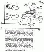
T1 is one of the missing components in Martin patent. I have some EDCORs to use. Also ordered a few 6BA6 , probably use 6SN7 for input follower and output buffer.
T1 is one of the missing components in Martin patent. I have some EDCORs to use. Also ordered a few 6BA6 , probably use 6SN7 for input follower and output buffer.
Attachments

- Status
- This old topic is closed. If you want to reopen this topic, contact a moderator using the "Report Post" button.
- Home
- Live Sound
- Instruments and Amps
- Martin real-time compressor