Hi all,
not a new theme for sure, but I would like to introduce you to my Version of a true-bypass mod for a Boss stompbox, in this case a SD-1 that is sitting on my floorboard.
There are lots of pros and cons for a hardwired bypass, in my case this seemed appropriate because the SD-1 is already being driven by a TS-9. The TS will not see a mod because it is about 30 years old and therefore left as it is.
So the SD-1 was the candidate. I wanted to do a mod that should be easily reversible, and would not incorporate metalwork to fit a mechanical switch. So it was to become a relay switch.
Actually it was just a try, but it worked out fine and simply was left in its "prototype" stadium. This may excuse for the rather crude workmanship...
Basically, I simply tapped one output of the flip-flop to control a small-signal darlington transistor. The darlington is convenient for a determined switching level and allows the use of a large base resistor, so it will not interfere with the operation of the FF. The transistor is driving a miniature small-signal DPDT relay, I used an Omron G6S.
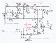
This is the schematic of the SD-1, with the mods added:

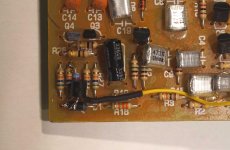
The transistor is fitted directly to the board, the blue base resistor can be seen underneath and is soldered to the transistor base above the case of D1. The emitter is grounded at the anode of D1, the yellow wire coming from the relay:

The input signal is wired directly to the relay, from then either to the output jack or to the input. The SD's input is grounded by a rather large resistor Rin to avoid pops when switching the relay.
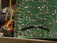
I simply put it on the solder side to some convenient grounding point. Other than in the schematic, the resistor is directly wired to terminal 3, should not make much difference anyway. on the left side is the relay:

On the output side, I felt the buffer was not necessary for me, so the output signal is being taken directly from the Level pot. So pot's grounding point has to be removed from the circuit's virtual ground on terminal #1 to common ground.
The output of the original buffer is left open, so the whole FET switching is completely removed from the signal chain. All this can be done without cutting traces or removing components, just by some rewiring of the board's terminals.

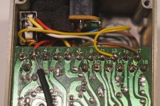
This picture shows the terminals.
The wire from the input now runs over Re1a.
The level potentiometer ground wire was moved from #1 to #17, its wiper going directly to the active contact of R1b, the output of which is wired directly to the output jack by the original wire taken from #12.
I tested and liked it. So it stayed as it was, with some foam fixing the relay.
The sound of the otherwise mostly unchanged SD-1 is now more open when bypassed, with a little more "bite" when engaged. Although this does not matter on the floorboard, it still could be powered with a battery, with shortened battery life of course. The downside is that switching is not 100% click-free, this could possibly be improved, but absolutely no problem for me in a stage situation.
This mod of course can be adopted for lots of Boss and non-Boss stompboxes sharing a similar topology, including good ol' Tube Screamer of course.
Also, the usual mods in the clipping stage are not affected.
Critics and questions welcome!
Cheers,
Georg
not a new theme for sure, but I would like to introduce you to my Version of a true-bypass mod for a Boss stompbox, in this case a SD-1 that is sitting on my floorboard.
There are lots of pros and cons for a hardwired bypass, in my case this seemed appropriate because the SD-1 is already being driven by a TS-9. The TS will not see a mod because it is about 30 years old and therefore left as it is.
So the SD-1 was the candidate. I wanted to do a mod that should be easily reversible, and would not incorporate metalwork to fit a mechanical switch. So it was to become a relay switch.
Actually it was just a try, but it worked out fine and simply was left in its "prototype" stadium. This may excuse for the rather crude workmanship...
Basically, I simply tapped one output of the flip-flop to control a small-signal darlington transistor. The darlington is convenient for a determined switching level and allows the use of a large base resistor, so it will not interfere with the operation of the FF. The transistor is driving a miniature small-signal DPDT relay, I used an Omron G6S.
This is the schematic of the SD-1, with the mods added:

The transistor is fitted directly to the board, the blue base resistor can be seen underneath and is soldered to the transistor base above the case of D1. The emitter is grounded at the anode of D1, the yellow wire coming from the relay:

The input signal is wired directly to the relay, from then either to the output jack or to the input. The SD's input is grounded by a rather large resistor Rin to avoid pops when switching the relay.
I simply put it on the solder side to some convenient grounding point. Other than in the schematic, the resistor is directly wired to terminal 3, should not make much difference anyway. on the left side is the relay:

On the output side, I felt the buffer was not necessary for me, so the output signal is being taken directly from the Level pot. So pot's grounding point has to be removed from the circuit's virtual ground on terminal #1 to common ground.
The output of the original buffer is left open, so the whole FET switching is completely removed from the signal chain. All this can be done without cutting traces or removing components, just by some rewiring of the board's terminals.

This picture shows the terminals.
The wire from the input now runs over Re1a.
The level potentiometer ground wire was moved from #1 to #17, its wiper going directly to the active contact of R1b, the output of which is wired directly to the output jack by the original wire taken from #12.
I tested and liked it. So it stayed as it was, with some foam fixing the relay.
The sound of the otherwise mostly unchanged SD-1 is now more open when bypassed, with a little more "bite" when engaged. Although this does not matter on the floorboard, it still could be powered with a battery, with shortened battery life of course. The downside is that switching is not 100% click-free, this could possibly be improved, but absolutely no problem for me in a stage situation.
This mod of course can be adopted for lots of Boss and non-Boss stompboxes sharing a similar topology, including good ol' Tube Screamer of course.
Also, the usual mods in the clipping stage are not affected.
Critics and questions welcome!
Cheers,
Georg
Last edited: